


EB AT-RP-4GU EN
3-1
Design and principle of operation
3 Design and principle of operation
The AIR TORQUE 4
th
Generation Upgrade Series (4
th
GU) ac-
tuators are devices for remote operation (on/off or modula-
ting duties) of different industrial valves such as ball valves,
butterfly valves and plug valves.
The actuators are available in two configurations: spring re-
turn and double acting.
1. DOUBLE ACTING
Refer to Fig. 3-1.
In case of the double acting configuration air pressure will be
necessary for both strokes (A and B).
Fig. 3-1
“2“
“4“
“2“
“4“
A
B
2. SINGLE ACTING
Refer to Fig. 3-2.
When air pressure is supplied through port “2“ (A‘) into the
actuator body, the linear force applied on the piston surface
generates the pinion rotation, driving the valve to a defined
position. At the same time the actuator springs are compres-
sed.
When air pressure is discharged (B‘), the springs are auto-
matically released, driving the rack and pistons back to the
original position and thus the valve to the fail-safe position.
Fig. 3-2
“2“
“4“
“2“
“4“
A‘
B‘
The actuators can be controlled by different options:
−
direct mounting of control devices (for example a solenoid
valve or a manifold) with NAMUR interface,
−
threaded connections (to pressurize port “2“ and “4“) wi-
th air lines from separate electro-pneumatic control sys-
tem.
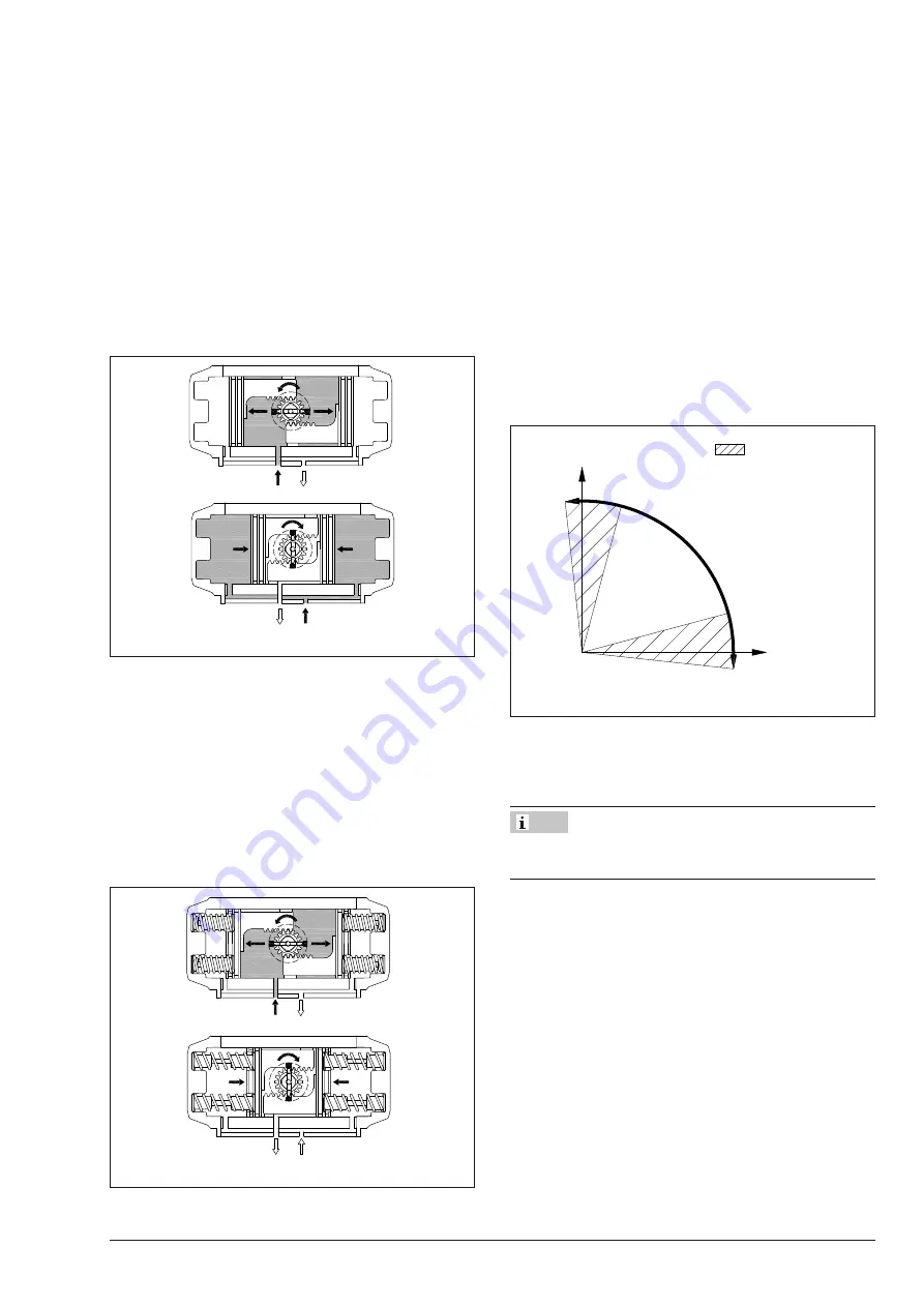
3.1 Direction of action and fail positions
The standard rotating direction for the 4
th
GU actuators is
clockwise to close.
Standard 4
th
GU actuators are designed for 90° rotating
angle, with travel stop allowing adjustment (Fig. 3-3) for -5°
up to +15° on the close position and for +5° up to -15° on the
open position. For AT045U stroke adjustment is only available
on request.
Fig. 3-3
0°
90°
95°
-5°
15°
75°
Available stroke
adjustment
For single acting actuators in case of pressure, power or
signal failure the springs drive the actuator in the fail position
that can be FAIL OPEN or FAIL CLOSE.
If the actuator is controlled by a control system the FAIL positi-
on may be different from FAIL OPEN or FAIL CLOSE.
Î
Refer to the actuator model technical data for the FAIL po-
sition.
Î
Refer to section 2.1 ‘Actuator nameplate sample‘ (Table
2-1, position 11) for the fail action and direction of rotati-
on available options.
Note
Summary of Contents for AT045U
Page 4: ...4 EB AT RP 4GU EN...
Page 8: ...1 4 EB AT RP 4GU EN Safety instructions and measures...
Page 10: ...2 2 EB AT RP 4GU EN Markings on the device...
Page 18: ...5 4 EB AT RP 4GU EN Mounting and assembly...
Page 20: ...6 2 EB AT RP 4GU EN Start up...
Page 22: ...7 2 EB AT RP 4GU EN Operation...
Page 24: ...8 2 EB AT RP 4GU EN Malfunctions...
Page 37: ...10 2 EB AT RP 4GU EN Decomissioning...
Page 41: ...12 2 EB AT RP 4GU EN Repairs...
Page 43: ...13 2 EB AT RP 4GU EN Disposal...
Page 45: ...14 2 EB AT RP 4GU EN...
Page 50: ...EB AT RP 4GU EN 15 5 Annex...
Page 51: ...15 6 EB AT RP 4GU EN...
Page 52: ...EB AT RP 4GU EN 15 7...


