Manual HD EN
0909e
Modifications reserved. Date 03.2017.
No guarantee for accuracy.
Older data sheets are invalid.
8.4)
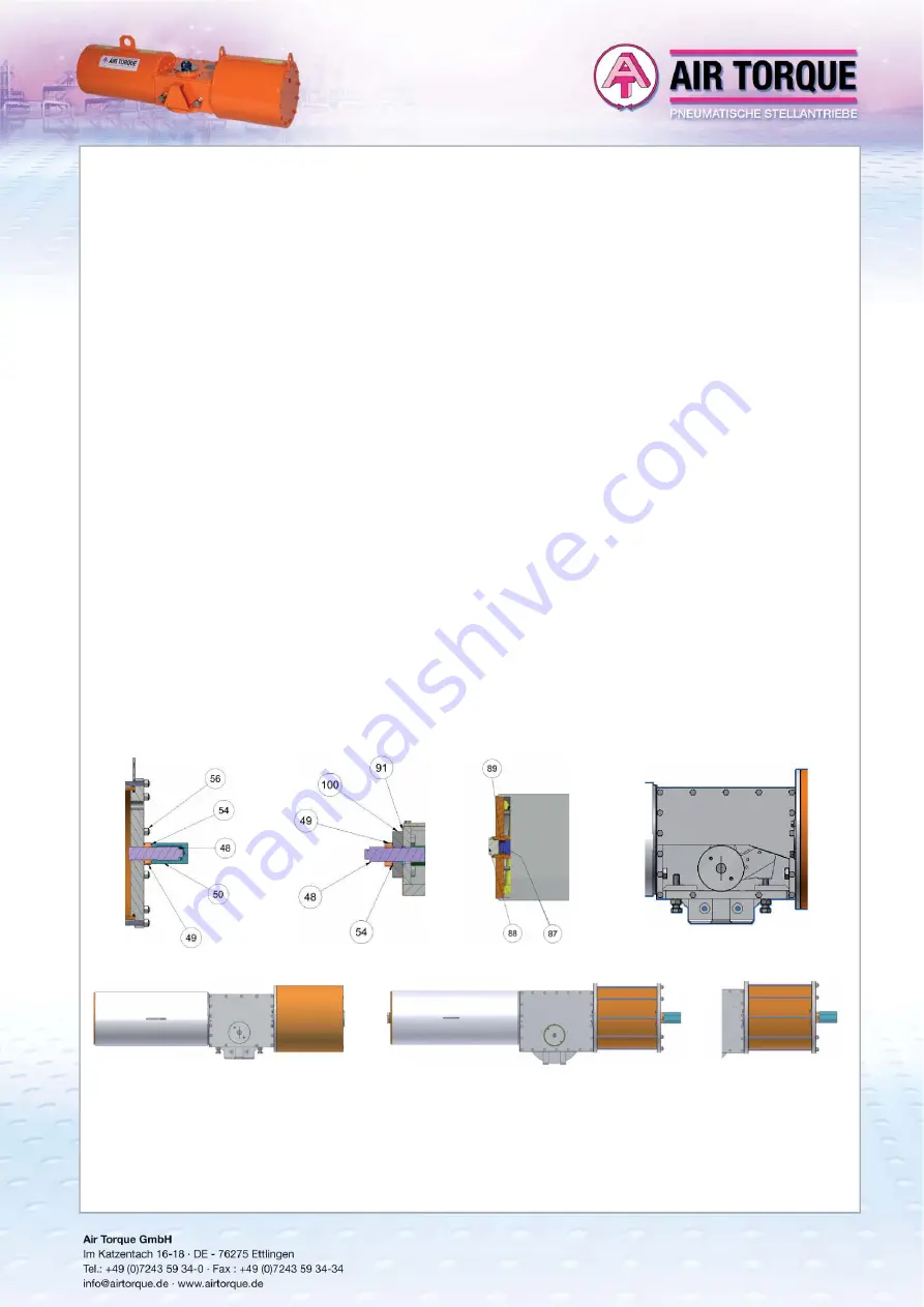
Assembling of the external group adjustment (only for Double Acting actuators with external stroke adjustment - option „B“) fi g. 2.
8.4.1)
Place the module gasket (13) in the center of the sleeve (M7)
8.4.2)
Screw the hexagonal screws (21) in the Central Module and in the end plate DA (100) from the inside of the Central Module, if any.
8.4.3)
Screw in the plate DA (100) the screw (48) with the nut (49). 8.4.4) Adjust the stroke (see par. 9)
8.5)
Closing of the cover and mounting of the position indicator
8.5.1)
Make sure that the Power and Spring Modules are correctly assembled 8.5.2) Place the cover gasket (12)
8.5.3)
Place the cover (2) on the Central Module and screw the hexagonal screws (23). 8.5.4) Fix the indicator to the Central Module screwing the hexagonal screws (22)
9)
STROKE ADJUSTMENT
AIR TORQUE actuators AT-HD series, have, in both starting and ending position of the stroke, a stoper that allows to achieve an adjustment of +/-5° in both 0° and 90° positions.
Warning:
Before proceeding with the stroke adjustment make sure that the actuator is in one of the two stroke positions, completely open (90°) or completely closed (0°). For a
correct valve operation, it is important that the travel stops of the actuator are correctly adjusted depending on valve type and function in order to avoid an incorrect
valve operation or valve damage.
The instructions below refer to the stroke adjustment for actuators with standard rotation – clockwise to close „CW“:
Depending on stroke adjustment option available, follow the instructions below to performe the actuator stroke adjustment
9.1)
Stroke adjustment in closed position (0°) fi g. 1 and fi g. 4:
9.1.1)
Unscrew the cover (50), of the screw if any.
9.1.2)
Loosen the nut of the screw (49), for Central stroke adjustment, loose the nut (103) of the right screw (counterclockwise to close for actuator seen from above).
9.1.3)
Slightly pressurize Port 2 of the Power Module to remove the load from the adjustment screw (50 or 102), otherwise actuator damage may occur, and adjust the position
of
the
stroke.
9.1.4)
Tighten the adjustment nut (49 or 103).
9.1.5)
Relieve the pressure from the Power Module to test the stop position of the stroke (for Spring Return actuators).
9.1.6)
If necessary, repeat the steps above.
9.1.7)
Screw the cover of the screw (50), if any.
9.2)
Stroke adjustment in open position (90°)
9.2.1) Double Acting actuator: fi g. 2 and fi g. 4:
9.2.1.1)
Loosen the nut of the screw (49), for Central stroke adjustment, loose the nut (103) of the left stop cap screw (102). Actuator seen from above.
9.2.1.2)
Slightly pressurize Port 4 of the Power Module to remove the load from the screw (48 or 102), otherwise actuator damage may occur, and adjust the
position of the stroke
9.2.1.3)
Tighten the adjustment nut (49 or 103)
9.2.1.4)
Relieve the pressure from Port 4 from the Power Module and supply Port 2 to test the stop position of the stroke.
9.2.1.5)
If necessary, repeat the steps above
9.2.2) Spring Return actuator: fi g. 3 and fi g. 4:
9.2.2.1)
Remove the plug (88) and the lock screw (89), if any
9.2.2.2)
Make sure that the Power Module is not pressurized to ensure that the spring is fully extended; otherwise actuator damage may occur
9.2.2.3)
If the central adjustment is available loosen the nut (103) of the left stop cap screw (102). Actuator seen from above.
9.2.2.4)
Adjust the position of the stroke with the cap screw (87) or, if Central stroke adjustment available, with the left stop cap screw (102). Actuator seen from above.
9.2.2.5)
Slightly pressurize Port 2 of the Power Module with enough air so that a complete stroke can be obtained. Check the stop position of the stroke.
9.2.2.6)
Screw the adjustment nut 103, if any.
9.2.2.7)
If necessary, repeat the steps above.
9.2.2.8)
Screw the lock screw (89) and the plug (88), if any.
10) PERIODICAL
CHECKS
•
Check that the actuator strokes correctly and within the require cycle time.
•
Check that the operating media supply pressure value is within the maximum allowable values for the actuator and for the application.
•
Visually inspect the external modules of the actuator to detect damages if any,
•
Check that there are no leakages in the pneumatic parts or hydraulic parts.
•
Remove the dust and/or the dirt from all actuators surfaces because they could inhibit the cooling of the actuator thus increasing the actuator temperature above the
maximum
allowable
limit.
•
Check the surfaces of the actuator to detect scratches/absence of paint which could compromise the corrosion protection; if necessary, repair only with appropriate paints.
External stroke adjustment Power
Module, fi g. 1
OPTION A: Central Stroke Adjustment, fi g. 5
OPTION B: External Stroke Adjustment, fi g. 6
OPTION C: Power Module with tie rod, fi g. 7
External stroke adjustment Central
Module (only for Double Acting), fi g. 2
External stroke adjustment Spring
Module, fi g. 3
External stroke adjustment Central
Module, fi g. 4
HEAVY-DUTY
Scotch-Yoke Pneumatic Actuators
MANUAL


