Air Liquide T 150i AC/DC Owner'S Manual Download Page 6

6

EQUIPMENT INSTALLATION AND MAINTENANCE MUST BE PERFORMED IN COMPLIANCE 

WITH LOCAL SAFETY STANDARDS.

• INSTALLATION AND MAINTENANCE OPERATIONS MUST BE PERFORMED BY QUALIFIED PERSONS ONLY.

• BEFORE INSTALLING the power source, check that the power socket satisfies ampere and voltage require-

ments (see data table plate). ENSURE that the socket is protected by appropriate fuses and automatic
switches.

• CONNECT an approved standard plug corresponding to the system socket to the power supply cable.

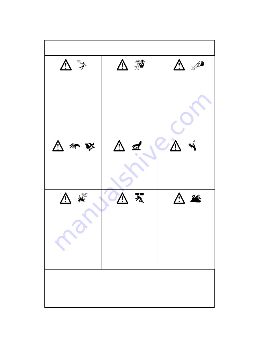
Electric shock could be fatal

1. Never touch exposed electrical

parts. 

2. Switch off and disconnect the

power source before installing
or opening.

3. Installation may be performed

by qualified persons only. 

4. Installation procedure must

comply with national electricity
standards and all other relevant
regulations. 

Fumes and gases may represent
a safety hazard. 
Fumes and gases generated dur-
ing welding may be dangerous if
inhaled over a long period of
time. 

1. Keep clear of fumes.  

2. Ventilate welding area or wear a

breathing mask. 

3. Install a natural or forced air

ventilation system in the work
area.

Use a protective mask with suit-
able glass filter (at least NR10) to
safeguard eyes.  

1. Wear appropriate eye, ear and

body protection equipment.  

2. Protect face, ears and neck dur-

ing welding operations. Advise
other persons in the vicinity to
look away and stand clear of arc
rays and hot metal. 

The positioning of welding equip-
ment on inflammable surfaces
could lead to fire outbreak or
explosion.  

1. Never position equipment on

combustible or inflammable
surfaces.   

2. Do not install equipment in the

vicinity of inflammable liquids. 

A falling power source or other
equipment may cause serious
injury to persons or damage to
objects.   

1. Always make use of the handle

to lift power source (applies to
portable models).   

2. Use eye bolts and adequate lift-

ing equipment to raise the
power source.  

WELDING MAY CAUSE FIRES OR
EXPLOSIONS. Never weld near
inflammable materials.   

1. Beware of weld flame. Always

keep a fire extinguisher close at
hand.    

2. Never place welding equipment

on inflammable surfaces.  

3. Do not weld in closed containers.

4. Let welding equipment and

material cool before handling
them.

Moving parts may cause injury.   

1. Keep clear of hazardous areas,

such as moving rollers.    

2. Keep all doors, panels and 

covers closed and in place. 

Hot areas may cause injury.  

Let the power source or other
parts cool before performing
any maintenance or servicing.  

Welding wire may cause injury.  

Do not point the torch toward
any part of the body, other per-
sons or any type of metal when
unwinding welding wire.  

Summary of Contents for T 150i AC/DC

Page 1: ...hnical specifications and the wiring diagrams contained in this owner s manual are valid only for the model that has the part number indicated below T 150i AC DC T 150i AC DC ALW M170500182 Air Liquid...

Page 2: ...RINCIPAL SAFETY STANDARDS 5 2 SPECIFICATION AND DESCRIPTION 2 1 SPECIFICATIONS 7 2 2 DESCRIPTION 7 2 3 DUTY CYCLE AND OVERHEATING 8 2 4 VOLT AMPERE CURVES 8 3 OPERATION 3 1 FRONT PANEL CONTROLS 9 3 2...

Page 3: ...in wet areas or standing on metal surfaces 11 Always turn off welding equipment that is not being used Do not leave welding equipment unattended SIGNIFICANT DC VOLTAGE exists after the removal of inpu...

Page 4: ...lways wear a protective mask 3 If the ventilation system is inadequate use an air respirator 4 Beware of gas leaks Shielding gases such as argon are heavier than air and when used in small spaces will...

Page 5: ...FIELDS As welding current flows through welding cables it can cause electromagnetic fields To reduce mag netic fields use the following procedures 1 Keep cables close together by twisting or taping t...

Page 6: ...iate eye ear and body protection equipment 2 Protect face ears and neck dur ing welding operations Advise other persons in the vicinity to look away and stand clear of arc rays and hot metal The posit...

Page 7: ...rrent regulation and thermal overload protection assist the welding operator in perform ing smooth and consistent welds Built in anti stick hot start and arc force will ensure ease of operation and in...

Page 8: ...duty cycle can damage the unit and void the warranty 2 4 VOLT AMPERE CURVES Volt ampere curves show the maximum voltage and amperage output capabilities of the welding power source Curves of other se...

Page 9: ...slowly reduced to zero based on the time that is set on the crater time control When the foot control is released the second time welding current is dis abled Spot Timer Control When the selector on...

Page 10: ...inues to run until the unit has cooled down 9 POSITIVE WELD OUTPUT RECEPTACLE For Stick welding using electrodes that operate on DCEP Direct Current Electrode Positive connect the electrode cable to t...

Page 11: ...ructed and that there is no risk of obstruction during operation 4 Avoid areas where dust or other objects could be sucked into the system 5 Equipment must not obstruct corridors or work activities of...

Page 12: ...control to the remote 14 pin receptacle located on the front panel of the unit 5 Connect the TIG torch power cable to the neg ative receptacle on the unit 6 Connect the ground cable to the positive r...

Page 13: ...oper type and size of tungsten electrode Use properly prepared tungsten Check and reverse electrode polarity check and correct poor connections to workpiece Shield welding zone from drafts Check shiel...

Page 14: ...14 6 T 150i AC DC ELECTRICAL DIAGRAM...

Page 15: ...15 7 T 150i AC DC SPARE PARTS LIST...

Page 16: ...16...

Reviews: