6
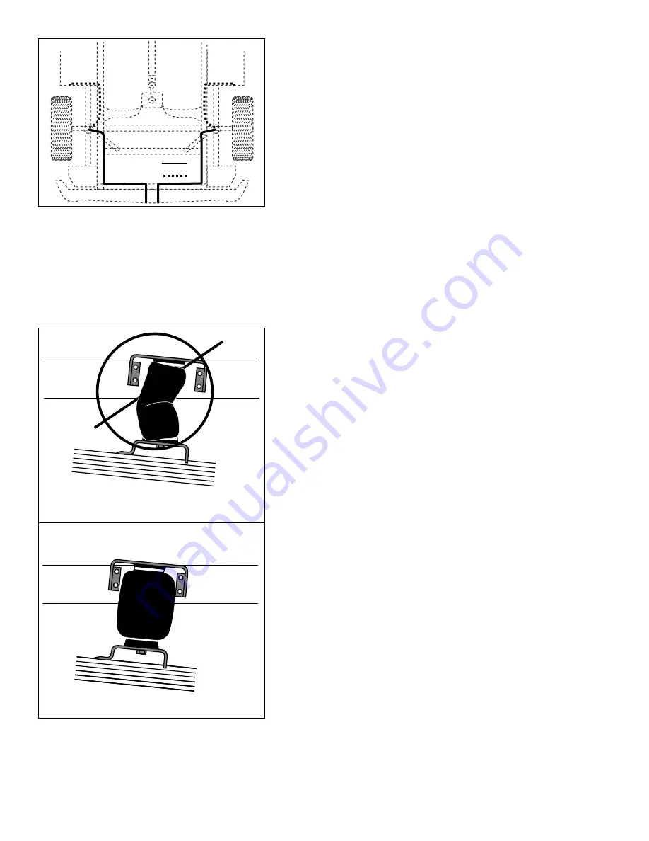
12. Route air line along frame from the inflation valve location to the
air springs (Figure 9). Use the provided clips and self tapping
screws to attach to the outside of the frame rail and the air line
sleeves to protect the air line when routing through existing holes
in the frame. It is not necessary to drill a hole for this type of
self tapping screw. Simply drive the screw through the frame
section. Attach air line to chassis with the provided plastic straps
where possible.
CAUTION: To prevent the air line from melting, keep it at least
12 " from the exhaust system.
13. Cut off excess air line squarely. Install the air line into the fitting.
This is a push to connect fitting. Push and slightly turn the cut
end of the air line into the fitting as far as it will go. There is a
definite “click” that can be heard and or felt when the air line is
seated. The air line should go in
9
/
16
". It is now installed.
14. VERY IMPORTANT: With the bottom and top of the air spring
still loose, inflate the air spring to approximately 10 p.s.i. By
using the slotted adjustment in the lower bracket align the air
spring so that there is a symmetrical cushion of air around the
lower base. This can be accomplished by pressing all around
the air spring to feel an air gap between rubber and piston. Adjust
by tapping it inboard or outboard for proper alignment (Figure
10).
15. Tighten the lower end by holding the Bolt with a 1
1
/
6
" wrench
and turning the air spring by hand. Use no tools, hand tight is
sufficient. It may be necessary to let some of the air out of the
air spring in order to turn it.
16. If L-bracket was used for the lower bracket to hook over, then
retighten U-bolts to 115 ft–lbs. Tighten lower bracket U-bolts to
16 ft–lbs.
17. Now tighten the upper nylon nut (4 ft–lbs). Do not overtighten.
18. Inflate to 30 p.s.i. Check all fittings and inflation valve core for
leaks with a liquid solution of
1
/
5
dish soap to
4
/
5
water. Check
once again to be sure you have clearance all around the air
spring at its fully inflated diameter (4.6").
19. Recheck air pressure after 24 hours. A 2 – 4 p.s.i. loss after
initial installation is normal. If pressure has dropped more than
5 p.s.i. retest for leaks with soapy/water solution. Please read
and follow the Maintenance and Operating tips. Check to see
that the sleeve rolls back down over the bottom piston after the
vehicle is lowered (Figure 10).
Option 1
Option 2
Figure 9
Not correct: Misaligned or not inflated
(acceptable during assembly)
Correct finished installation: inflated
Figure 10


