background image

6

MN-337

TO PREVENT THE ELEMENTS FROM ENTERING THE CAB AREA.

3.  Connect wiring harness #1 to the back of the gauge panel. 

a.  With your thumb against the front side of the switch, connect the wire by pushing 

the female connectors onto the blade connectors on the switch. 

b.  Match the air line by the color band on the air line to the color band on the tees. 

c.  Push the air lines onto the “T” fittings until the air line completely covers the barb 

(fig. 4). Lubricating the air line will ease pushing the air line over the barb. 

d.  Do not connect the power wire at this time.

e.  Wiring  harness  #1  also  connects  the  gauge  panel  to  the  low  pressure  sensor 

assemblies. The low pressure sensors protect the air springs from failure resulting 

from low pressure in the unloaded condition. These sensors are preset to maintain 

a MINIMUM pressure of 5 psi in the air springs. The sensors measure the pressure 

in each spring and turn on the compressor if the pressure falls below 5 psi. 

The low pressure sensors are preassembled onto wiring harness #1. The sensors should 

be located under the dash inside the vehicle and secured with the provided tie straps. 

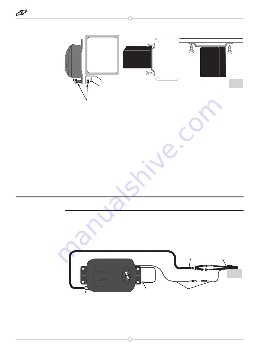
4.  Push the air line coming from the “Y” assembly onto the barb fitting on the compressor. 

Make sure the air line covers all barbs. A small amount of water or lubricant and pushing 

with a slight circular motion will ease installation (fig. 7).

5.  Connect the check valves and power wire on harness #2 to the “Y” assembly as shown 

in fig. 1. Do not overtighten the check valve connector. Hand tight is sufficient.

6.  Route wiring harness #2 from the compressor. 

a.  Use existing grommets in the floorboard or firewall to route the harness from the 

compressor to the low pressure sensors on harness #1. 

NOTE

fig. 7

Power (red) wires

Air line

Harness #2

Ground

Barbed fitting/

check valve

fig. 6

Compressor

Compressor

Floor plan

Frame

L-bracket

Supplied self 

tapping screw

¼” Bolt and nut will need to 

be provided if the L-bracket 

is fabricated.

Load Controller II

Summary of Contents for Load Controller II 25812

Page 1: ...ectiveness and safety please read these instructions completely before proceeding with installation Failure to read these instructions can result in an incorrect installation INSTALLATION GUIDE Kit 25812 5 psi Low Pressure Sensor Dual Gauge ...

Page 2: ......

Page 3: ... 2 Installation Diagram 3 Hardware List 3 Installing the Load Controller II System 4 Getting Started 4 Recommended Compressor Locations 4 Step by Step Installation 5 Warranty and Returns Policy 8 Replacement Information 9 Contact Information 9 TABLE OF CONTENTS 1 ...

Page 4: ... along with other weight limits as well as tire rim size and inflation pressure data is shown on the vehicle s Safety Compliance Certification Label Payload The combined maximum allowable weight of cargo and passengers that the truck is designed to carry Payload is GVWR minus the Base Curb Weight NOTATION EXPLANATION Hazard notations appear in various locations in this publication Information whic...

Page 5: ... Fuse Uses 3 16 smaller Female Push On Connector fig 1 Item Part Description Qty A 16060 Compressor 1 B 26159 Panel assembly 1 C 26061A Y assembly 1 D 26087 Harness 1 1 E 26110 Harness 2 1 F 20225 Hose 25 Item Part Description Qty G 20035 Grommet 1 H 24542 Fuse 1 I 24543 Fuse 1 J 24561 Fuse adapter 1 K 24643 Red wire 16 L 20788 Black wire 8 HARDWARE LIST Missing or damaged parts Call Air Lift cust...

Page 6: ...rovided tie straps All preassembled gauge panels have been 100 leak function tested DO NOT attempt to tighten loosen or adjust any fittings or connections This will likely cause a leak or malfunction and void the warranty RECOMMENDED COMPRESSOR LOCATIONS Important LOCATE COMPRESSOR IN DRY PROTECTED AREA ON VEHICLE DIRECT SPLASH OR ExCESSIVE MOISTURE CAN DAMAGE THE COMPRESSOR AND CAUSE SYSTEM FAILU...

Page 7: ...does not provide enough room to use a drill to drive the screws in It may be necessary to use the mounting brackets as a template to drill 13 64 holes through the frame first and then use a 7 16 nut driver to install the self tapping screws Attach the ground wire to one of the screws fig 1 c For box frames In some cases the frame section will not be wide enough to mount the compressor legs flat to...

Page 8: ...re in each spring and turn on the compressor if the pressure falls below 5 psi The low pressure sensors are preassembled onto wiring harness 1 The sensors should be located under the dash inside the vehicle and secured with the provided tie straps 4 Push the air line coming from the Y assembly onto the barb fitting on the compressor Make sure the air line covers all barbs A small amount of water o...

Page 9: ...in fig 7 d Route the air line across the chassis from the far side over the exhaust system heat shields and along the frame up to the compressor Avoid heat sources sharp edges and tight bends 9 Connect the power wire from harness 1 a Route it to the vehicle fuse box b Use a test light to determine which open terminal accessory etc works only when the key is in the on or accessory position or refer...

Page 10: ...legal rights and you may also have other rights that vary from state to state Some states do not allow limitations on how long an implied warranty lasts or allow the exclusion or limitation of incidental or consequential damages The above limitation or exclusion may not apply to you There are no warranties expressed or implied including any implied warranties of merchantability and fitness which e...

Page 11: ...ct our customer service department by calling 800 248 0892 Monday through Friday 8 a m to 7 p m Eastern Time For calls from outside the USA or Canada our local number is 517 322 2144 For inquiries by mail our address is PO Box 80167 Lansing MI 48908 0167 Our shipping address for returns is 2727 Snow Road Lansing MI 48917 You may also contact us anytime by e mail at sales airliftcompany com or on t...

Page 12: ... com Thank you for purchasing Air Lift products the professional installer s choice Printed in the USA Need Help Contact our customer service department by calling 800 248 0892 Monday through Friday 8 a m to 7 p m Eastern Time For calls from outside the USA or Canada our local number is 517 322 2144 Register your warranty online at www airliftcompany com warranty ...

Reviews: