Technical Support
1-800-248-0892
Ext. 2
4
“The Choice of the
Professional Installer”
For Technical Assistance call 1-800-248-0892
Thank you for purchasing Air Lift Products
Mailing Address:
Street Address:
AIR LIFT COMPANY
AIR LIFT COMPANY
P.O. Box 80167
2710 Snow Rd.
Lansing, MI 48908-0167
Lansing, MI 48917
Local Phone: (517) 322-2144
Fax: (517) 322-0240
http://www.airliftcompany.com
Printed in the USA
4. Start with a higher pressure and decrease in five pound increments
to determine the best ride and handling for your particular vehicle.
5. Increases in pressure can be made to compensate for additional
load and trailers, etc. Higher pressures can be used when the vehicle
is in storage to relieve the leaf springs.
VII. Operating from the Cab
The air springs should be inflated to the specified air pressure as discussed
in the air spring inflation procedure.
Whenever load and weight distribution change, simply adjust the pressure
in the air springs to maintain a level vehicle. Through use of the level
control system the air springs can be used to compensate for an uneven
campsite and uneven load distribution. The air pressure is manually
controlled individually by the control panel located on the dash.
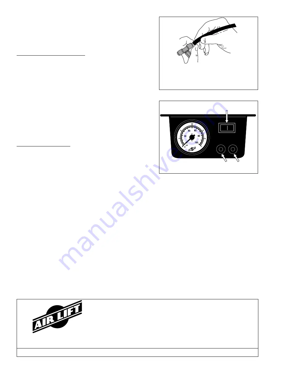
1. To inflate the air springs and raise that side of the motor home, depress
the toggle switch on the control panel. The compressor will turn on
automatically to increase the pressure as indicated on the gauge.
Once the desired pressure is reached release the button and the
compressor will shut-off (Figure 9).
2. To deflate the pressure and lower that side of the motor home, depress
the down button to deflate to desire pressure (Figure 9).
VIII. Troubleshooting
Check the inflation pressure weekly, air spring bellows will permeate (loss
of pressure through the rubber wall) at the approximate rate of 3-4 p.s.i. per
week. Leakage at a higher rate indicates a leak.
To find a leak:
1. Inflate the system to 100 p.s.i.
2. Spray all fittings with a solution of
1
/
5
dish soap to
4
/
5
water.
a.
Check inflation valve: valve core and air line connections. If leak
is found in the valve core, tighten. It may be replaced with standard
Figure 8
Figure 9
Toggle Switch
Deflate Buttons
tire valve core. Fittings sometime only need tightening.
b.
Check elbow fitting where threaded into bellows (all threaded connections must have pipe sealant applied) and air line
connection. If a leak is found where elbow is threaded into bellows, remove the fitting and clean thoroughly and apply
fresh liberal coat of pipe sealant. If a leak is found in the barbed fittings, reduce air pressure to zero and tighten threaded
connections or remove air line, cut off one inch, and reinstall.
3. Spray bellows to determine if leak exists. The bellows are not repairable and must be replaced if a leak is found in them.
4. If leak still cannot be found deflate and remove entire unit. Inflate to 15 p.s.i. only and submerge in water.
5. If leakage is suspected in the control panel, inflate the system to 100 p.s.i. and follow steps above. The fittings at the tee and
back of the control panel should also be checked with soapy solution. Most leakage can be cured by disassembly,
inspection and reassembly of fittings.
6. If compressor fails to function, check 20 amp fuse and ground connection. Repair and replace as necessary.
7. If electric motor runs, but compressor doesn’t function check to make sure solenoid valves are opening correctly.
Cut off excess air line squarely. Install the air line into the
fitting. Push the cut end of the air line into the self-locking
fitting as far as it will go while slightly turning. A definite
click can be heard and/or felt when the air line is seated.
Air line should go in approximately
9
/
16
".


