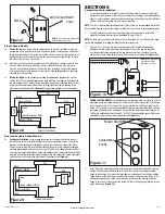


Single Speed Models
2a.
Wiring the Fan:
Run wiring from an approved wall switch (not included) carrying the
appropriate rating. One neutral (white), one ground (green or bare copper), and one hot
(black lead connected to the switch). Secure the electrical wires to the housing with an
approved electrical connector. Make sure you leave enough wiring in the box to make
the connection to the fan’s receptacle.
2b. From where you have chosen to access the fan’s junction box, connect the white wire
from the house to the white wire from the fan’s receptacle. Connect the black wire
from the wall switch to the black wire from the fan’s receptacle. Connect the ground
wire from the house to the green wire from the fan housing
(Figure 8).
Use approved
methods for all connections.
2c.
Wiring the Lights:
Using a properly grounded standard duplex toggle switch (such as
Leviton 5224-2W, not included) connect the black wire from the supply to one side of the
top and bottom switch. Connect the red wire (light) from the fan housing to the other side
of the top switch and connect the purple wire (night light) from the fan housing to the
other side of the bottom switch.
(Figure 8).
Use approved methods for all connections.
Dual and Variable Speed Models
3a.
Continuous Ventilation:
For two speed fans wired for continuous ventilation, connect
the White wire of the fan to the White (Neutral) wire from the power source. Connect the
ground wire from the house to the green wire from the fan housing. Connect the Black
wire of the fan to the Black wire (Hot) from the power source. Using a properly grounded
standard duplex toggle switch (such as Leviton 5224-2W, not included) connect the Black
wire from the supply to one side of the top and bottom switch. Connect the Red wire (light)
from the fan housing to the other side of the top switch and connect the Purple wire (night
light) from the fan housing to the other side of the bottom switch
(Figure 9).
www.airkinglimited.com
6728056 Rev. C 5-14
3 of 12
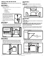
SECTION 6
Completing the Installation
1.
Use a sealant appropriate for contact with the building materials present and for the
temperature requirements of the installation to prevent air leakage from unconditioned
spaces is recommended. If gaps between unit housing and ceiling are great, additional
material (backing rod, ceiling material) may be required.
NOTE:
This fan is rated for direct insulation contact (Type IC) and it is recommended that this fan
be completely covered by insulation in order to reduce heat loss or gain to unconditioned space.
2.
If the fan’s blower assembly was removed during the wiring process, reinstall the
blower by reversing the directions in
Section 5
(Wiring),
Step 1b.
NOTE:
An extra 2-pin connector with tape over it may be present. This is utilized for the boost
speed. See
Section 9
(Activating the Boost Speed) for more details.
3.
Plug the fan’s 2 pin and 3 pin quick connect motor cords into the corresponding
receptacle located on the wire compartment cover. Connect the two pin connector
from the humidistat compartment to the two pin connector from the side of the wire
compartment cover. These cords will only fit one way into the receptacles
(Figure 10).
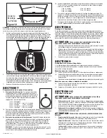
4.
VARIABLE SPEED MODELS:
First decide if you will require more or less than 65 CFM of
ventilation on the low speed setting. If it is less than 65 CFM place the Low CFM Range
rocker switch on the 30-60 range. If it is more, place the low CFM range rocker switch
on the 70-120 range. Once you have decided on the minimum required airflow, the fans
low speed CFM level can be adjusted by using either the lower adjustment knob (30-60
CFM) or the middle adjustment knob (70-120 CFM). The desired high speed CFM can be
adjusted by using the upper most adjustment knob
(Figure 11).
5.
Install the ceiling mounting flange to cover any gaps which exist between the housing
and the finished ceiling. Remove the two screws that connect the ceiling mounting
flange to the housing. Put sealant (not provided) on inside edge of the ceiling mounting
flange to ensure that the flange is sealed to the ceiling. Line up the screw holes in the
ceiling mounting flange with the screw holes on the inside of the housing and press
flange in place so it is tight against the ceiling. Reinstall ceiling flange mounting screws
inside the housing
(Figure 12)
.
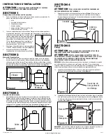
Screw
Wire Compartment
Cover
Figure 7
NOTE:
Wire compartment configuration
will be dependent on model.
Figure 8
Supply from house
Black
Neutral (White)
Ground (Green or Bare)
Fan
Black
Neutral (White)
Green
Switch
Black
Purple
Red
Switch
Figure 9
Supply from house
Black
Neutral (White)
Ground (Green or Bare)
Fan
Black
Neutral (White)
Green
Switch
Black
Purple
Red
Figure 10
NOTE:
Wire compartment
configuration will be
dependent on model.
30
40
50
60
LO
W
LO
W
HI
GH
70
90
10
0
120
80
11
0
13
0
Bo
ost
Figure 11
Adjustment
Knobs
Rocker Switch


