AIR GAP Fluidmaster 6000 Series Installation Manual Download Page 1

1

4

5

7

8

6

2

3

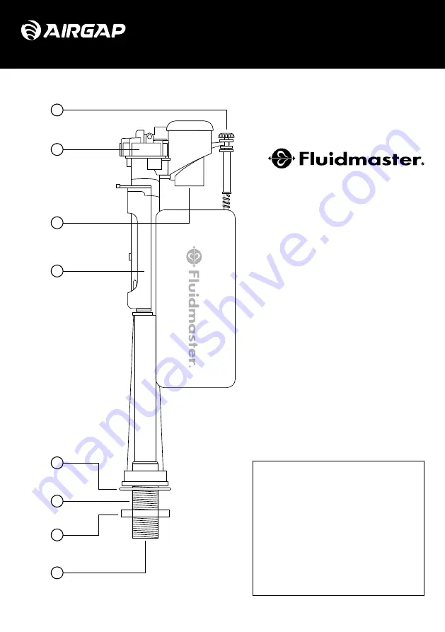
6000 Series AirGap™ Installation Guide

Bottom entry valve assembly

Float adjustment screw

1.

Cap

2.

Anti-siphon vortex generator

3.

Float chamber & locking sleeve

4.

Washer

5.

1/2” or 3/8” BSP threaded shank 

6.

Nut

7.

Pre-fitted flow controller and filter

8.

INSTALL WITH CONFIDENCE

Summary of Contents for Fluidmaster 6000 Series

Page 1: ...ation Guide Bottom entry valve assembly Float adjustment screw 1 Cap 2 Anti siphon vortex generator 3 Float chamber locking sleeve 4 Washer 5 1 2 or 3 8 BSP threaded shank 6 Nut 7 Pre fitted flow controller and filter 8 INSTALL WITH CONFIDENCE ...

Page 2: ...Series AirGap Installation Guide Side entry valve assembly Float adjustment screw 1 Cap 2 Anti siphon vortex generator 3 Float chamber 4 Washer 5 1 2 or 3 8 BSP threaded shank 6 Nut 7 Pre fitted flow controller and filter 8 ...

Page 3: ...t the stop Valve assembly is jammed Ensure float adjustment screw and attached components are free to move vertically Locking sleeve is up bottom entry only Ensure float chamber and locking sleeve is down locked position Flow controller and filter is blocked Isolate and disconnect from water supply Remove flow controller and filter from threaded shank to clean Certification compliance Note Datum l...

Page 4: ... your cistern Drain all water from the cistern and disconnect valve supply pipework Step 3 Remove the old valve from the cistern and ensure the fixing hole area is clean and free of debris or anything which may impair sealing Step 1 Turn off the water supply to the toilet using isolation valve or mains stopcock ...

Page 5: ... will benefit from the removal of the flow controller and filter Mains water or pumped installations require the filter restrictor to be fitted Note For side entry valve ensure the flow controller and filter is fitted in the orientation as shown Step 5 Check that the sealing washer is pushed fully onto the threaded shank ...

Page 6: ...h mechanism Step 7 Tighten the nut by hand and then by to of a further turn with an appropriate spanner wrench to achieve an adequate seal Be careful not to rotate the valve and do not overtighten Step 8 Turn the water supply back on ensuring there are no leaks and the flush is operating correctly Note There will be a delay between float lift and valve shut off and initial cycles of a new valve ma...

Page 7: ...m entry valve only When the valve has been adjusted to the required height push the float chamber and locking sleeve back down to relock the mechanism Note Ensure the float chamber and locking sleeve are returned to the locked position before restoring the water supply Step 10 for bottom entry valve only To make larger adjustments to the height turn the water supply off and unlock the float chambe...

Page 8: ... and property damage and 2 void fluidmaster warranty Do not overtighten nuts or cistern bowl may crack Always use quality Fluidmaster parts when installing or repairing Fluidmaster will not be responsible or liable for use of non Fluidmaster parts during installation or repair It is the responsibility of the installer to ensure work is carried out in accordance with all appropriate regulations and...

Reviews: