background image


AIPHONE 

5


03.07.15 – V1.0 

 
The JPTLIIPA must connect to a modem or to a private box. 
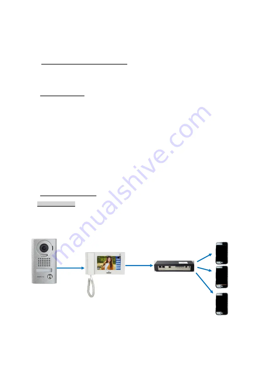
When a call is placed on the Door Station, the image from this one appear on the video station and 
send automatically the video onto 2 Smartphone. Without answer with the Smartphone, the JPTLIIPA 
goes back into Stand-by mode into the next call. 
 

1 – BASIC USER OPERATION


Few functioning parameter are available and can be set following the customer needs. For that, some 
options can be program (see Installation Manual §4). 


1.1 VISITOR CALL


When the door Button is push, the call is send onto 2 Smartphone throw your interface and your 
private box (or modem). 
 

If one of the 2 Smartphone answer

, the communication is establish between you and the visitor.  

You are inform that you are in communication mode by a screen change on your smartphone. 

You can choose the “Door opening” function by choosing the “Key” Symbol. 
For open the door, you must choose between 3 Door relay onto a confirmation screen: 

-


Contact#1 with the 1st « Key » symbol 

-


Contact#2 with the 2

nd

 « Key » symbol 

-


Optional Relay with « Activate option » for using the JPTLIIPA Relay 

 
The communication is stopped when press the « end communication » Button or when the 
communication timer is over (3 minutes). 
 

If no Smartphone answer after a delay of 50sec or if they are already in communication, the 
interface goes into Stand-By Mode until a next call. 


1.2 MODE SELECTION


Mode « OFF »


The selector is on ‘OFF’. 
In this mode, if the visitor presses the Call-button, only JP4MED is ringing. 


Smartphones 

Door Station 


           Master Station   

              Interface 


(5 maxi) 


Summary of Contents for JPTLIIPA

Page 1: ...AIPHONE 22 07 15 V1 1 JPTLIIPA IP INTERFACE FOR JP SYSTEM OPERATION MANUEL...

Page 2: ...moisture and humidity extremes such as bathrooms cellars greenhouses etc Places where the temperature is quite low such as inside a refrigerated area or in front of an air conditioner Places subject t...

Page 3: ...Interface 4 Power supply 5 Quick set up INSTALLATION Location for mounting JPTLIIPA interface can be placed on a furniture or fixed on the wall to do this action it must be fixed with 2 crews with pl...

Page 4: ...he AIPHONE JP series door station to 2 smartphones with Andro d or Apple software ATTENTION To get an audio or video good reception your smartphone must receive phone calls by WIFI or 3G 4G 3G minimum...

Page 5: ...unication is establish between you and the visitor You are inform that you are in communication mode by a screen change on your smartphone You can choose the Door opening function by choosing the Key...

Page 6: ...lay 1 5 seconds Door1 Name Operating time of the relay 2 5 seconds Door2 Name Operating time of the relay 3 JPTLIIPA 5 seconds Optional Relay Name Operating time of the relay 4 JPTLIIPA 5 seconds Opti...

Page 7: ...re is well plug on the modem or on the private box Check the smartphone has been registered Check the AiphoneJP application is launch Check the Status Led is blinking 1 time each seconds if not please...

Page 8: ...AIPHONE 8 03 07 15 V1 0 Fonction Smartphone Application Launching Launching Screen Running Application you can receive call To return to Stand by Mode push the IPhone Home Button...

Page 9: ...AIPHONE 9 03 07 15 V1 0 To permit the application remains in stand by mode you must activate the AiphoneJP notifications...

Page 10: ...lling screen screenshot form the visitor Push Audio Video communication begin If you push the JPTLIIPA go Stand by Mode Caution The call will not send to the voice mail If the area is not covert by 3G...

Page 11: ...deactivate the smartphone speaker with The symbol below become red the speaker is deactivate Activate or deactivate the micro private mode with The symbol below become red the micro is deactivate Act...

Page 12: ...and optional relay During the call press the key symbol This screen appear Move the green symbol to the grey symbol For opening the 1st Entry choose For opening the 2nd Entry choose For activate the o...

Page 13: ...AIPHONE 13 03 07 15 V1 0 Alarm Functioning Alarm Activated Screen When the key you will have the message Alarm activated and the following screen...

Page 14: ...tions 1 Ethernet network 2 Bus JP Telephones 1 Smartphones Android or IPhone Power supply 12V DC 0 5A Consumption Stand by 350mA when relay is on 430mA Standards EN60950 EN55022 Edition 98 Classe B EN...

Page 15: ...AIPHONE 15 03 07 15 V1 0...

Page 16: ...AIPHONE 16 03 07 15 V1 0 Distributed par AIPHONE Print in France...

Reviews: