


12
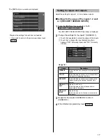
Connecting external devices (using the option connectors)
The option connectors of this station can be used with the following external devices. After connecting, program setting to control the
devices with this station. (
→
P. 16)
CAUTION
To prevent shorts, cut unused lead wires at insulation.
•
Be sure to perform an operation check after the connection to check for miswiring.
•
b1
b2
b3
b4
V+
V
SW
SW
S1
S1E
S2
S2E
S3
S3E
1
Security/utility input 1,
Request to exit 1 (External door release input 1)
Connect a security sensor, call button, door release button,
etc. to these inputs.
Input method
N/O or N/C dry closure contact (start
signal only detection method)
Detection
con
fi
rmation time
100 mS or more
Contact resistance
During N/O dry closure: Less than 700
Ω
During N/C dry closure: At least 15 k
Ω
Terminal short current Less than 10 mA
Voltage between
terminals
Less than 5 V DC (when open between
terminals)
2
Security/utility input 2,
Request to exit 2 (External door release input 2)
Same as
1
.
3
Security/utility input 3, External talk input
Same as
1
except below.
A foot switch can be connected to operate the
•
TALK or
END
function hands-free.
A door release button cannot be connected t
•
o these
inputs.
4
Option output
Connect an alarm sensor, light, etc. to these outputs.
Contact capacity:
Maximum overload: AC/DC 24 V, 1 A,
N/O dry closure contact
Minimum overload: DC 5 V, 100 mA
5
Video out
Outputs video signals to an external monitor, DVR, etc.
NTSC/PAL, 1 Vp-p/75
Ω
•
Wiring distance: 3 m (10 feet)
•
NOTES:
A video signal is output while receiving a call from,
•
communicating with, or monitoring a door station.
(A playing image will not be output.)
When a video signal is output, this station may produce a noise,
•
depending on the installation environment.
When the image on the screen is adjusted by touching
•
ADJUST
(see page 21 of "OPERATION MANUAL"), the
video signal output from this connector is also adjusted.
When a video door station or camera is connected to this station
•
via a long distance adaptor, the format of video signals output
from this connector differs depending on the connected video
door station or camera as follows. Connect a device compatible
with the format of video signals output from this connector.
Aiphone video door station: NTSC
•
NTSC camera: NTSC
•
PAL camera: PAL
•
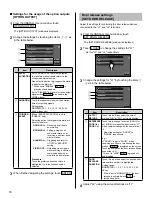
6
Door station selecting signal output
Connect the RY-3DL multiple door release adaptor to these
outputs to add a selective door release system.
Refer to page 11 for connection method.
*
Brown
Red
Blue
White
Gray
Black
Orange
Black
Yellow
Black
Purple
Black
Yellow
Orange
Red
Brown
12-pin option connector
4-pin option connector
5
Video out
4
Option output
1
Security/utility input 1, Request to exit 1 (External door release input 1)
2
Security/utility input 2, Request to exit 2 (External door release input 2)
3
Security/utility input 3, External talk input
6
Door station selecting signal output
(Unused)
To 12-pin
connector
To 4-pin
connector


