DEIMOS GERMANIUM FUZZ
25
FINAL ASSEMBLY & BIASING
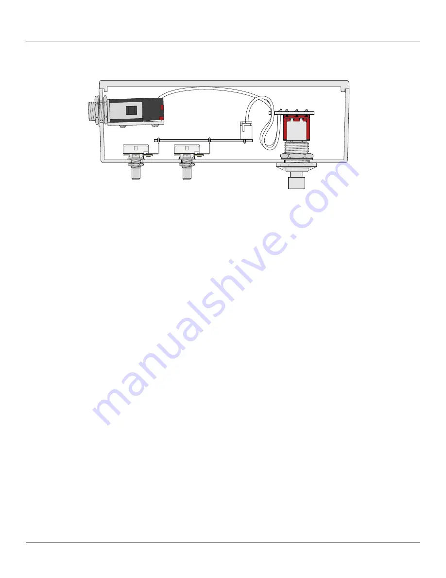
After everything is in place, just plug the 3 wire assemblies into their respective headers and make sure
they’re secure. That’s it! Here is a cross-section of the inside of the completed pedal.
At this point, you have completed the full circuit as far as the electrons are concerned, but we still need
to bias the transistors before it will sound right.
Biasing
The trimmers allow for easy biasing of the transistors without having to swap out resistors.
One thing to understand is that the Q2 bias trimmer actually adjusts the bias of Q3 as well, while the Q3
pot only adjusts Q3. So, always bias Q3 using the Q2 trimmer, and only use Q3’s bias adjustment if you
need to fine-tune it further.
To start, turn both bias trimmers all the way down (counterclockwise). Then, with a multimeter, touch
the black and red leads to the two pads marked “Q3 TEST”. Turn up the Q2 trimmer until the Q3 test pad
reads
-8.5V
(either positive or negative depending on which lead is touching which pad).
Then, with the black lead touching ground, measure each leg on all three of the transistors. You’re
looking for something near these voltages.
•
Q1:
Emitter 0V (left leg); Base -0.05V (middle leg); Collector -8.5V (right leg)
•
Q2:
Emitter 0V (left leg); Base -0.07V (middle leg); Collector -0.15V (right leg)
•
Q3:
Emitter -0.1V (left leg); Base -0.15V to -0.35V (middle leg); Collector -8.5V (right leg)
The voltages don’t need to be anywhere near exact, this is just a benchmark. Let your ears be the judge.
After biasing, if Q2’s voltages are off, you may need to bias Q3 independently. Re-adjust the Q2 trimmer
until Q2 is in the proper range, then adjust the Q3 trimmer until Q3’s voltages look right.
Testing
Plug in a 9-volt supply and test it out with a guitar and an amplifier.
Test the bypass switch a few times, then start turning the controls and see if everything sounds OK. If it
works, great! If not, don’t be discouraged. See page 29 for troubleshooting info.


