background image


  20 

RS232 Character Set 

Because of the need for XON/XOFF handshake it is possible to send ASCII coded data only; 
binary blocks are not allowed. Bit 7 of ASCII codes is ignored, i.e. assumed to be low. No 
distinction is made between upper and lower case characters in command mnemonics and they 
may be freely mixed. The ASCII codes below 20H (space) are not used. In this manual 20H, etc. 
means 20 in hexadecimal. 

USB Interface & Driver Installation (QPX1200SP only) 

The instrument firmware can be updated in the field through the USB port. This does not need 
the driver described here. It requires a PC software utility provided by the manufacturer, and uses 
a HID driver that will already be installed on the PC. If that is the only USB functionality required, 
download the package containing the firmware update together with the PC utility from the 
manufacturer, and follow the instructions included. 

Using the USB interface for remote control requires a Communications Device Class driver on 
the PC to provide a virtual COM port instance. In Windows a suitable driver is provided by 
Microsoft, but it is not installed by default. The data (.INF) file to control the installation is provided 
on the Product Documentation CD delivered with the unit; however the same driver is also used 
by many other instruments from this manufacturer and may already be known to the PC. 

To install the driver for the first time, first switch the unit on, and then connect the USB port to the 
PC. The Windows plug and play functions should automatically recognise the attachment of new 
hardware to the USB interface and (possibly after searching the internet for some time) prompt 
for the location of a suitable driver. Follow the Windows prompts and point to the CD, then the 
sub-directory for this product, and then to the USB Driver sub-directory below that. The file is 
named USB_ARM_VCP_xxx.INF, where xxx is a version number. (A readme.pdf file will also be 
found in that directory if further assistance is needed.)  

In some cases Windows will not complete this procedure (especially recent versions which 
search the internet first, looking for the unique Vendor ID and Product ID), in which case the 
instrument will show in Device Manager as “not working properly”. If this happens, select this 
device, right click and choose “update driver software...” and then “browse this computer for 
driver software...” and then locate the .INF file on the CD as described above. 

Once Windows has installed the device driver it will assign a COM port number to this particular 
unit. This number will depend on previous COM port assignments on this PC, and it may be 
necessary to use Device Manager to discover it. Each instrument has a unique USB identifier 
which is remembered by the system, so it will receive the same COM port number whenever it is 
attached to the same PC (regardless of the physical interface socket used), even though the 
COM port will disappear while the instrument is disconnected or switched off. Other instruments 
will receive different COM port numbers.  

Note that a different PC will not necessarily assign the same COM port number to a particular 
instrument (it depends on the history of installations), however Device Manager can be used to 
change the assignments given. 

This virtual COM port can be driven by Windows applications (including a terminal emulator) in 
exactly the same way as any standard COM port, except that the Baud rate and other settings 
are unnecessary and are ignored. Some old applications might not function with COM port 
numbers 3 or 4, or above 9. In this case, use Device Manager to change the allocation given. 
Once it is installed, the driver will be maintained by Windows Update in the usual way. 

LAN Interface (QPX1200SP only) 

The LAN interface is designed to comply with 1.4 LXI Core 2011 and contains the interfaces and 
protocols described below.  Since it is possible to misconfigure the LAN interface, making it 
impossible to communicate with the instrument over LAN, a LAN Configuration Initialise (LCI) 
mechanism is provided via a recessed switch on the rear panel to reset the unit to the factory 
default.  The default setting is for the instrument to attempt to obtain settings via DHCP if 

Summary of Contents for QPX1200S

Page 1: ...QPX1200S QPX1200SP PowerFlex DC Power Supplies INSTRUCTION MANUAL ...

Page 2: ...s 7 Initial Operation 9 Manual Operation 11 Remote Operation 18 Remote Commands QPX1200SP only 28 Maintenance 33 Note The latest revisions of this manual device drivers and software tools can be downloaded from http www aimtti com support This manual is 48511 1530 Iss 11 ...

Page 3: ...elope the output becomes unregulated CV CC or UNREG mode indication in display Output Switch Electronic with ON indication Preset voltage and current displayed when off Output Terminals Front panel safety terminals accepting 6mm wire diameter 6mm plugs or 8mm spades at 50 Amps max or 4mm plugs at 30 Amps max Duplicate rear panel terminals Sensing Switchable between local and remote Screwless remot...

Page 4: ...t voltage greater than approximately 3 3V The maximum voltage that can be applied without damaging the unit is 20V and the input should not be taken negative by more than 3V User can set LOGIC IN via the keyboard to enable the output disable the output or be ignored when it is activated LOGIC OUT is an isolated rear panel open collector output that will sink up to 2mA when activated switch closure...

Page 5: ...0 USB Standard USB 2 0 hardware connection LAN Ethernet 100 10base T hardware connection 1 4 LXI Core 2011 compliant GPIB Conforming with IEEE488 1 and IEEE488 2 Remote Command Processing Time Typically 100ms between receiving the command terminator for a step voltage change at the instrument and the output voltage beginning to change GENERAL AC Input 110V 240V AC 10 50 60Hz Installation Category ...

Page 6: ...prohibited The protective action must not be negated by the use of an extension cord without a protective conductor When the instrument is connected to its supply terminals may be live and opening the covers or removal of parts except those to which access can be gained by hand is likely to expose live parts The apparatus shall be disconnected from all voltage sources before it is opened for any a...

Page 7: ...fer to the power rating information on the equipment or in the Specification WARNING THIS INSTRUMENT MUST BE EARTHED Any interruption of the mains earth conductor inside or outside the instrument will make the instrument dangerous Intentional interruption is prohibited Mounting This instrument is suitable both for bench use and rack mounting It is delivered with feet for bench mounting The front f...

Page 8: ...ithin specification Logic Input LOGIC IN is connected to the input of an isolating opto coupler via an 820Ω resistor in series The input is activated by an input voltage greater than approximately 3 3V between LOGIC IN and LOGIC COMMON up to 20V may be applied to the input but it should not be taken negative by more than 3V The active input current will be between 2mA and 25mA depending on applied...

Page 9: ...ccepts a standard USB cable The Windows plug and play functions should automatically recognise that the instrument has been connected If the correct driver is not found follow the Windows on screen prompts and install the required files from the CD supplied LAN QPX1200SP only The LAN interface is designed to meet 1 4 LXI Lan eXtensions for Instrumentation Core 2011 Remote control using the LAN int...

Page 10: ...ser such that entry or control errors are minimised Where some of these features e g beeps are considered unnecessary by regular users the option exists to disable them see the Extra Functions section Under normal conditions the numeric keypad is disabled pressing any key will cause the buzzer to beep indicating an illegal operation To set a voltage with the keypad first press the V NUMERIC SET ke...

Page 11: ...ted are 1mV 10mV 100mV and 10mA 100mA 1A To disable the jog rotary control press the JOG SET OFF key reselecting JOG SET V or I will enable jog on the last used digit position Jog is not cancelled by using numeric entry or any of the SHIFT functions but it is disabled whilst that function is enabled Note that the dual display of the parameter being jogged is primarily of use if the output is ON wi...

Page 12: ...verts to the standard status mode Pressing ESCAPE at any time during the sequence or making no further key press within 10 seconds of the previous one will cause the display to return to its original reading before SET V was pressed Entering a voltage outside the range maximum including trying to enter 3 digits before the decimal point or trying to enter more than 5 digits will cause the buzzer to...

Page 13: ... lamp and the AMPS display will again change to two lines With the output ON the top line continues to show the actual output but the additional lower display now shows the present current limit in the lower display the JOG indicator is positioned under the digit that was last jogged Whilst the I SET lamp is lit each further press will move the JOG indicator one digit to the left the selection wra...

Page 14: ... but this is inevitably increased by the resistance of the connecting leads and the contact resistance between terminals and leads At high currents this can result in significant differences between the indicated source voltage and the actual load voltage even two 2mΩ connecting leads will drop 0 2V at 50 Amps for instance This problem can be minimised by using short thick connecting leads but whe...

Page 15: ... that the output terminals are rated at 60A maximum if several outputs are operated in parallel to source higher currents than this the junction should be made at a separate point not one of the terminals Over Voltage Protection Over Voltage Protection OVP can be set from 1 0V to 65 0V If the output voltage exceeds the set OVP the output is immediately turned off typically within 100µs thus avoidi...

Page 16: ...ure is suspected the cause of the fault should be rectified and the unit allowed to cool before the AC supply is turned on again Note that an over temperature trip shuts down the primary side of the instrument and it is that condition that is detected and causes the fault message to be displayed However other faults may occur which would also cause the primary side to shut down and these will not ...

Page 17: ...ntly saved set ups on the Store screen The store location to be used can be selected directly by pressing any key 0 9 or by scrolling to the appropriate store number in the list using the JOG SET control the selected store is indicated by the square brackets at that location Press OK to store the set up at the selected location the screen returns to the standard status display A full store can be ...

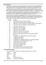
Page 18: ... the factory default option for example if 26 is selected 20 25 and 27 are all deselected Code Function 10 Output always off at power up factory default 11 Output status at power up same as at last power down 20 LOGIC OUT closed for Output ON open for Output OFF factory default 21 LOGIC OUT closed for Output OFF open for Output ON 22 LOGIC OUT closed for any trip 23 LOGIC OUT open for any trip 24 ...

Page 19: ...ing the address is essential for GPIB operation but use can be made of the ADDRESS command over any of the other interfaces to easily identify which instrument is being controlled by a particular COM port for RS232 or USB or TCP socket for LAN Note that the LAN interface also has a separate Identify function accessible from the instrument s web pages that flashes the instrument s display until the...

Page 20: ...nly RS232 Interface Connector The 9 way D type serial interface connector is located on the instrument rear panel The pin connections are as shown below Pin Name Description 1 RI Passively asserted V through 10kΩ 2 TXD Transmitted data from instrument 3 RXD Received data to instrument 4 CTS 5 GND Signal ground 6 RTS Passively asserted V through 10kΩ 7 DSR No internal connection 8 DTR 9 CD No inter...

Page 21: ...e cases Windows will not complete this procedure especially recent versions which search the internet first looking for the unique Vendor ID and Product ID in which case the instrument will show in Device Manager as not working properly If this happens select this device right click and choose update driver software and then browse this computer for driver software and then locate the INF file on ...

Page 22: ... LAN Status is displayed in the top left hand corner of the display during normal operation It is not shown on all menus There are 4 possible indications No LAN If the unit cannot detect any connection to a LAN e g the cable is unplugged then the LAN status indicator is Configuring The unit has detected a LAN connection but is not yet configured e g is waiting for DHCP The LAN status indicator is ...

Page 23: ...services provided by the instrument are http _http _tcp and lxi _lxi _tcp VISA Resource Name Because of the limited support for VXI 11 Discovery Protocol only the instrument must be referred to by its raw socket information when used in software packages which communicate via a VISA resource name For example an instrument at IP address 192 168 1 100 would normally have a VISA resource name of TCPI...

Page 24: ... be placed in the Query Error Register and the response formatter to be reset thus clearing the output queue The parser will then start parsing the next PROGRAM MESSAGE UNIT from the input queue See the Status Reporting section for further information The IEEE 488 2 DEADLOCK error is handled as follows If the response formatter is waiting to send a response message and the input queue becomes full...

Page 25: ...gle connections so represent one interface instance each LAN however allows for multiple simultaneous connections and therefore represents multiple interface instances Two interface instances are allocated to the two TCP socket interfaces and one more is allocated to the Web page interface Having a separate model for each interface instance ensures that data does not get lost as many commands e g ...

Page 26: ...been encountered 100 The numerical value sent with the command was too big or too small Includes negative numbers illegal store numbers numbers 1 where only 0 and 1 are allowed etc 101 A recall of set up data has been requested but the store specified contains corrupted data This indicates either a hardware fault or a temporary data corruption which can be corrected by writing data to the store ag...

Page 27: ... Not used Bit 6 RQS MSS This bit as defined by IEEE Std 488 2 contains both the Requesting Service message and the Master Status Summary message RQS is returned in response to a Serial Poll and MSS is returned in response to the STB command Bit 5 ESB The Event Status Bit This bit is set if any bits set in the Standard Event Status Register correspond to bits set in the Standard Event Status Enable...

Page 28: ...eyboard active The instrument parameters at power on are the same as at last switch off with the exception of the output status By default this is always off at power on but the user may change this to the same at power on as at switch off Status Model ...

Page 29: ... is defined as character codes 00H to 20H inclusive WHITE SPACE is ignored except in command identifiers e g C LS is not equivalent to CLS The high bit of all characters is ignored The commands are case insensitive GPIB Remote Command Formats GPIB input to the instrument is buffered in a 256 byte input queue which is filled under interrupt in a manner transparent to all other instrument operations...

Page 30: ...r with no fractional part i e an integer NR2 A number in fixed point format e g 11 52 0 78 etc CPD CHARACTER PROGRAM DATA CRD CHARACTER RESPONSE DATA Instrument Specific Commands For commands specified as WITH VERIFY the operation is completed when the parameter being adjusted reaches the required value to within 5 or 10 counts whichever is the greater If the value fails to settle within these lim...

Page 31: ...where 1 ON 0 OFF OPALL NRF Set all outputs on off where NRF has the following meaning 0 OFF 1 ON In this instrument it has the same action as OP1 NRF SENSE1 NRF Set output sense mode where NRF has the following meaning 0 local 1 remote SAV1 NRF Save the current PSU set up to the set up store specified by NRF where NRF can be 0 9 RCL1 NRF Recall a set up for the PSU from the set up store specified ...

Page 32: ...d clear Query Error Register The response format is nr1 RMT Interface Management Commands LOCAL Go to local Any subsequent command will restore the remote state LOCALLOCKOUT NRF Sets the keyboard status where NRF has the following meaning 1 keyboard locked 0 keyboard active Note that this command only affects the keyboard not the other interfaces if required use IFLOCK to disable the other interfa...

Page 33: ...must be one of DHCP AUTO or STATIC IPADDR quad Sets the potential static IP address of the LAN interface as on the webpage The parameter must be strictly a dotted quad for the IP address with each address part an NR1 in the range 0 to 255 e g 192 168 1 101 NETMASK quad Sets the netmask to accompany the static IP address of the LAN interface The parameter must be strictly a dotted quad for the netm...

Page 34: ...securing screws and lift off the cover Replace the fuse with one of the correct type and refit the cover Note that the main function of the fuse is to make the instrument safe and limit damage in the event of failure of one of the switching devices If a fuse fails it is therefore very likely that the replacement will also blow because the supply has developed a fault in such circumstances the inst...

Page 35: ... Huntingdon Cambridgeshire PE29 7DR England United Kingdom Telephone 44 0 1480 412451 Fax 44 0 1480 450409 International web site www aimtti com UK web site www aimtti co uk Email info aimtti com Aim Instruments and Thurlby Thandar Instruments ...

Reviews: