background image

39

RC SERIES INSTALLATION MANUAL

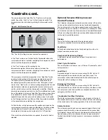
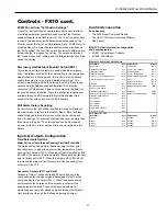
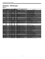
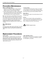
BACnet Variables

Controls - FX10 cont.

The variables will be listed with the point type and instance preced-
ing the variable name. 

Analog Input (Type 0)

0:1 

Space Temp


[Read only, shows the space temperature]

0:2 

Discharge Air Temp


[Read only, field mounted sensor unless supplied   


as a factory special]

0:3 

Effective Clg Setpt


[Read only, shows the active cooling setpoint]

0:4 

Effective Htg Setpt


[Read only, shows the active heating setpoint]

0:5 

Space Humidity


[Read]

0:6 

Water Coil Temp


[Read, shows the refrigerant temperature at its


coldest, for predictive freeze condition detection]

0:7 

Low Temp Limit


[Read, shows the water coil low temperature (freeze


sensing) limit that will result in unit shutdown.]

0:8 

ECM Cmd Output


[Read, shows the commanded speed (0-100%) of 


the ECM Blower]

0:9 

Alarms Enumerated


[Read only, 0=no alarms, 1=condensate alarm,


2=Compressor Hi Discharge Pressure alarm,


3=Compressor low Suction Pressure alarm,


4=Freeze sensing alarm, 8=Faulty Freeze 

Sensor  


alarm, 9=Loss of Charge]

0:10  AO2 Value


[Read, shows the output value (0-100%) of AO2]

Analog Output (Type 1)

1:1 

Space Setpoint


[Write, Raise and lower the heating and cooling


setpoints from a single command point(volatile, 


reverts to ‘uncommanded’ after power outage).]

1:2 

ECM Fan Ovrd


[Write, allows network direct control of the ECM 


blower speed (volatile, reverts to ‘uncommanded’ 


after power outage)]

1:3 

AO2 Override


[Write, allows network direct control of the Analog  


Output 2, volatile, reverts to ‘uncommanded’ after 


power outage)]

1:4 

Space temp Ovrd


[Write, allows the network to send space


temperature values to the heat pump controller, 


volatile, these will supersede any temperature    


sensor connected to the space temperature Analog 
 

Input.]

Analog Value (Type 2)

2:1 

Occupied Cool


[Write, Cooling setpoint in Occupied mode]

2:2 

Unoccupied Cool


[Write, Cooling setpoint in Unoccupied mode]

2:3 

Occupied Heat


[Write, Heating setpoint in Occupied mode]

2:4   Unoccupied Heat


[Write, Heating setpoint in Unoccupied mode]

2:5 

Temporary Occ Time


[Write, set the duration of the temporary occupancy 


timer which is initiated by pressing the button on the 


zone sensor]

2:6 

Remote Setpt Span


[Write, sets the offset range that the setpoint knob 


on the zone sensor may apply to the effective Htg/


Clg setpoints]

2:7 

Remote Setpt Bias


[Write, biases the entire readjust range of the


remote setpoint adjust to allow zeroing from the


network.]

2:8 

Space Temp Offset


[Write, Adds an offset to the Space Temp value for 


calibration]

2:9 

Dehumidify Setpt


[Write, sets the humidity value that will cause the 


heat pump to enter passive dehumidification]

2:10  Low Temp Limit Adj


[Write, sets the water coil low temperature (freeze 


sensing) limit for shutdown]

Binary Input (Type 3)

3:1 

Fan Cmd Status


[Read, show the commanded condition of the Fan


Output,Inactive=Off, Active=On]

3:2 

Comp Cmd Status


[Read, show the commanded condition of the 


Compressor Output, Inactive=Off, Active=On]

3:3 

Comp Hi Capacity Cmd


[Read, show the commanded condition of the ‘Hi 


Capacity’ Compressor control, Inactive=Off, 


Active=On.]

3:4 

Reversing Valve


[Read, show the commanded condition of the 


Reversing Valve Output, Inactive =Heating,


Active =Cooling]

3:5 

Accessory 1 Output


[Read, Shows the commanded value of the X1


(Accessory

3:8 

Alarm Status


[Read, shows the in alarm/out of alarm status, 


Inactive=Off, Active=On]

Summary of Contents for RC Series

Page 1: ...Installation Manual RC Series Geothermal Water Source Heat Pump R 410A Refrigerant 0 75 1 5 Tons Single Speed Installation Information Water Piping Connections Electrical Startup Procedures Troubleshooting Preventative Maintenance ...

Page 2: ......

Page 3: ...ing 17 Open Loop Ground Water Systems 18 Electrical Connections 19 Auxiliary Heat Ratings 19 Electrical Data 20 Fan Performance Table 20 Wiring Schematics 21 25 Controls 26 40 Startup Notes 41 Startup Checklist Unit Startup Steps 42 Operating Parameters 43 Operating Limits 43 Startup Troubleshooting Form 44 Pressure Drop 45 Preventive Maintenance 46 Replacement Procedures 46 ...

Page 4: ...ation only w t stat control option 2 5 FX10 w Open N2 Com Card only w t stat control option 2 6 FX10 w Lonworks Com Card only w t stat control option 2 7 FX10 w BacNet Com Card only w t stat control option 2 Vintage A Current Non standard Option Details SS Standard Option Air Coil Insulation Option 1 FormiShield Extended Range 2 FormiShield Standard Range 3 No Coating Extended Range 4 No Coating S...

Page 5: ...he packaging if necessary Units in question should also be internally inspected If any damage is noted the carrier should make the proper notation on the delivery receipt acknowledging the damage Water Piping The proper water flow must be provided to each unit whenever the unit operates To assure proper flow use pressure temperature ports to determine the flow rate These ports should be located at...

Page 6: ... 3 124 7 29 8 10 9 09 12 15 18 F B G I J C E D A H FILTER BRACKET FILTER BRACKET RIGHT RETURN TOP FRONT LEFT RETURN DETAIL B TWIST EXTENDED TAB BACK AND FORTH UNTIL TAB BREAKS OFF ONLY BREAK OFF TAB SAME SIDE AS GRILLE LID AS SHOWN DETAIL B TWIST EXTENDED TAB BACK AND FORTH UNTIL TAB BREAKS OFF ONLY BREAK OFF TAB SAME SIDE AS GRILLE LID AS SHOWN B A REMOVE PLASTIC STRIP FROM BROKEN TAB AND REPLACE...

Page 7: ... 4 124 7 29 8 10 9 09 12 15 18 REMOVE PLASTIC STRIP FROM BROKEN TAB AND REPLACE ON BROKEN EDGE OF LEG AS SHOWN H I J C F E A D G B RIGHT RETURN TOP FRONT LEFT RETURN DETAIL B TWIST EXTENDED TAB BACK AND FORTH UNTIL TAB BREAKS OFF ONLY BREAK OFF TAB SAME SIDE AS GRILLE LID AS SHOWN DETAIL A TWIST EXTENDED TAB BACK AND FORTH UNTIL TAB BREAKS OFF ONLY BREAK OFF TAB SAME SIDE AS GRILLE LID AS SHOWN RE...

Page 8: ...0 12 6 29 1 9 2 35 0 6 1 2 5 54 1 11 8 4 3 cm 139 7 32 0 73 9 23 4 88 9 15 6 6 4 137 4 29 8 10 9 09 12 15 18 FILTER BRACKET FILTER BRACKET A D E C H I J F B G A B RIGHT RETURN TOP FRONT LEFT RETURN DETAIL B TWIST EXTENDED TAB BACK AND FORTH UNTIL TAB BREAKS OFF ONLY BREAK OFF TAB SAME SIDE AS GRILLE LID AS SHOWN DETAIL A TWIST EXTENDED TAB BACK AND FORTH UNTIL TAB BREAKS OFF ONLY BREAK OFF TAB SAM...

Page 9: ...DE NORMAL BOILERLESS SWITCH OPTIONAL FAN OPTION SWITCH OPTIONAL BACK PLATE REQUIRED FOR DAMPER INSTALLATION OUTSIDE AIR DAMPER OPTION FIELD INSTALLED LOW VOLTAGE TERMINALS FX10 REMOTE WALL STAT OPTIONS ONLY OPTIONAL FUSED NON FUSED DISCONNECT OPTIONAL BALL VALVES OPTIONAL HOSE KITS CONDENSATE DRAIN CONNECTION FILTER HANDY BOX Dimensional Data Right Return Controls Detail ...

Page 10: ... 65 65 2 19 83 50 4 1 64 4 2 12 03 30 6 0 66 1 7 2 75 7 0 5 5 14 0 DAMPER OPENING Models 09 12 BLOWER ACCESS PANEL COMPRESSOR ACCESS PANEL 42 88 108 9 34 0 86 4 1 5 3 8 1 5 3 8 4 32 11 0 8 88 22 6 FILTER CONTROL PANEL 25 25 64 1 0 86 2 2 11 75 29 8 1 0 2 5 12 0 30 5 4 5 11 4 2 0 5 1 20 6 52 3 19 5 49 5 CONDENSATE DRAIN CONNECTION WATER OUT 1 2 FPT WATER IN 1 2 FPT OPTIONAL BACK PLATE COMPRESSOR AC...

Page 11: ...CONNECTION FILTER HANDY BOX OPTIONAL ELECTRIC HEAT OPTIONAL BACK PLATE REQUIRED FOR DAMPER INSTALLATION OUTSIDE AIR DAMPER OPTION FIELD INSTALLED CONTROL PANEL REMOVE FOR ACCESS TO CONTROL BOX DAMPER ON OFF SWITCH COMPRESSOR ACCESS PANEL REMOVED FOR CLARITY BOTH SIDES ELECTRIC HEAT MODE NORMAL BOILERLESS SWITCH OPTIONAL FAN OPTION SWITCH Dimensional Data Left Return Controls Detail ...

Page 12: ... COMPRESSOR ACCESS PANEL DAMPER OPENING 43 37 110 2 1 62 4 1 25 65 65 1 19 83 50 4 Models 09 12 8 88 22 6 34 0 86 4 1 50 3 8 1 50 3 8 4 32 11 0 42 88 108 9 BLOWER ACCESS PANEL COMPRESSOR ACCESS PANEL FILTER CONTROL PANEL 1 00 2 5 11 75 26 2 4 5 11 4 0 86 2 2 2 0 5 1 25 25 64 1 20 6 52 3 19 5 49 5 12 0 30 5 CONDENSATE DRAIN CONNECTION WATER OUT 1 2 FPT WATER IN 1 2 FPT 33 0 83 8 13 90 35 3 11 78 29...

Page 13: ...hims used Position backplate in desired equipment location To further reduce the operating sound level of the unit 1 8 inch thick rubber matting may be placed under the chassis to eliminate vibration on hard flooring surfaces Make sure back plate is level Mark and cut floor or wall penetrations for electrical wiring water and condensate piping Optional Electrical Disconnect and Motorized Outside A...

Page 14: ...tion system The supply and return water piping should be run through the wall or floor penetration and terminate with a ball valve The piping material used must comply with all local codes Refer to System Cleaning and Flushing procedures Pipe Locations Figure 2 CONSOLE CABINET CONSOLE CHASSIS CONDENSATE DRAIN LOCATION WATER CONNECTIONS TARGET AREA FOR WALL PENETRATION FUSED ELECTRICAL DISCONNECT O...

Page 15: ...ould be installed on both the supply and return water lines of the unit Flow control valves should be installed on the water discharge line It is recommended that P T ports be installed on the supply and return water lines Step 9 Set Unit Controls Locate the continuous fan cycle fan switch within the electrical compartment of the chassis and set to desired position Remote wall thermostat units do ...

Page 16: ...et repositioning pieces 4 1 2 and 3 into the locations directly opposite the original positions Secure by replacing mounting brackets Note Be sure that louvers on the grille assembly are facing the proper direction when replacing the grille section Replace grille frame assembly into cabinet and secure by replacing 5 mounting brackets Replace cabinet by sliding it down over the top of the chassis 6...

Page 17: ...ct the system from dirty water conditions Dirty water will result in system wide degradation of performance and solids may clog valves strainers flow regulators etc Additionally the heat exchanger may become clogged which reduces compressor service life and can cause premature unit failure In boiler tower application set the loop control panel set points to desired temperatures Supply power to all...

Page 18: ...iance in your area Note For open loop groundwater systems or systems that do not contain an antifreeze solution set SW1 Switch 2 to the WELL posi tion Refer to the Dip Switch Field Selection table Slow opening closing solenoid valves type VM are recommended to eliminate water hammer Water Quality In ground water situations where scaling could be heavy or where biological growth such as iron bacter...

Page 19: ...X2 X1 W2 Field Connections Unit Connections 24 VAC COMMON COMPRESSOR REVERSING VALVE FAN LOCKOUT SIGNAL SHUTDOWN NIGHT SETBACK LOAD SHED Requires common connections or 24 VAC for activation Red Black Yellow Orange Green Brown Blue Violet Pink Figure 5 Model Rated Voltage Voltage Min Max Heater Element Watts Fan Motor FLA Heater Element FLA Total Unit FLA Min Circuit Amp Max Fuse Brkr 09 12 208 60 ...

Page 20: ...500 fpm by 0 16 in wg Electrical Data Model Rated Voltage Voltage Min Max Compressor Fan Motor FLA Total Unit FLA Min Circ Amp Max Fuse HACR MCC RLA LRA 09 208 230 60 1 197 253 6 4 4 1 21 0 0 50 4 6 5 6 10 265 60 1 238 292 na 4 3 22 0 0 50 4 8 5 9 10 12 208 230 60 1 197 253 7 7 4 9 25 0 0 50 5 4 6 7 10 265 60 1 238 292 na 5 3 22 0 0 50 5 8 7 1 10 15 208 230 60 1 197 253 9 2 5 9 29 0 0 69 6 6 8 1 1...

Page 21: ...ite 20 Orange 14 Orange 21 Black 29 Red 30 Black Black 12 White 18 Red 11 Red 19 Red 17 24 V Accessory 24VAC Shutdown Red 15 Red 16 NOTE 1 T ST CC Compressor Contactor HP High Pressure Switch LP Low Pressure Switch RV Reversing Valve Coil ST Entering Air Temperature Sensor RB Blower Relay Black Black Red 11 Black 12 Red 17 Red 19 Black 25 White 28 Black 31 Red 32 Brown 26 RB 4 2 5 Red RV DT ON OFF...

Page 22: ...ack 27 RB 4 2 5 Red EH T2 T1 L2 White White L1 EH Normal RV DT ON OFF Damper Sw Damper Motor D Fan Mode Sw 4 5 2 E1 E1 AQ Blk Wht 24 Blk Wht 23 Black 22 White 18 Blue T6 NOTE 2 3 1 RB 3 1 Black 37 Blue 38 Blue Wht 36 Blue Wht 35 White 34 Blue T6 FS Yellow 44 Yellow 44 Brown 43 Yellow 13 Blue Tan 41 Blue 40 White 28 Blue 40 Brown 3 Tan 41 Brown 26 Green 00 Red 39 Gray 42 NOTE 3 NOTE 4 Violet 4 Viol...

Page 23: ...ON Current fault or Output display mode activated Normal Standard timings Well Open loop freeze sensing setting 30 F Normal Unit status display Normal Standard thermostat operation Normal Standard delay on call from compressor used Refer to LED Display Mode table for position of SW1 4 and SW2 LogicBoard DIP Switch Settings Normal Control Timing Table Blower offdelay Compressor on delay Shortcycle ...

Page 24: ...g information for specific thermostat hookup instructions Red Black 25 RB Gray 42 White 28 Black 29 Red 30 Damper Motor Off On DAMPER MODE DT D Blue Wht 35 MV Black 31 Red 32 Handi Box Ground Lug Unit Power Supply 208 230 60 1or 265 277 60 1 G C R Y1 O G L S Terminal Board X2 X1 W1 Red Bl ack Yellow Orange Brown Green NOTE 2 Violet Pink Bl ue 1 3 4 2 NOTE 1 ES Emergency Shutdown Black White Black ...

Page 25: ...reeze protection Field Zone Sensor Wiring 3 Acc 1 output is cycled with the compressor 4 Acc 2 output is cycled with the fan 5 R C Y1 O and G inputs are for use with a wall mounted thermostat A23 A13 A11 A21 A12 A25 A22 Open Jumper Closed Jumper 2 TB R C Y1 O G L X1 X2 24VAC 24V COM Alarm Acc 1 Acc2 Fan Rev Valve Comp SS AIC RS SC TO Setpoint Shift AI Com Room Sensor Sensor Com Temp Occ EHC T2 T1 ...

Page 26: ...cts Optional Medium User Interface MUI can be used as a field service tool Standalone Unit Mounted Digital Dial Sensor Remote Mounted Standard Thermostat Remote Mounted Sensor FX10 w N2 FX10 Control functions as both unitary heat pump control and DDC communica tion therefore detail operational and fault information is available to BAS Other features are same as FX10 with addition of Johnson Contro...

Page 27: ...is disabled Optional Versatec Microprocessor Control Features The Versatec microprocessor board provides control of the entire unit as well as outputs for status modes faults and diagnostics The control system is a microprocessor based control board that is located in the unit control box This feature is available for either unit mounted controls or optional remote wall mounted thermostat A 9 pin ...

Page 28: ...fault recognition delay 30 seconds Low pressure fault bypass delay 2 minutes Freeze sensing fault bypass delay 2 minutes Power on delay 5 minutes Normal Control Timing Operational Logic Blower off delay 5 seconds Compressor on delay 2 seconds Short cycle delay 15 seconds Miniumum compressor on time 5 seconds except for fault condition High pressure fault recognition delay Less than 1 second low pr...

Page 29: ...er Coil Low Temperature Freeze Sensing Condensate overflow sensing Lockout mode control Emergency shutdown mode Random start and short cycle protection Short Cycle Protection Allows a minimum compressor off time of four minutes and a minimum on time of two minutes Random Start A delay of 1 to 120 seconds is generated after each power up to prevent simultaneous startup of all units within a buildin...

Page 30: ... on from a BAS as needed An alarm history can be viewed through the MUI and will be held in memory until the unit is power cycled Relative humidity can be read by a 0 5VDC humidity sensor that is displayed over the network If you are using an ECM fan motor the control can enable dehumidification mode based on a set point in the control The dehumidification set point itself can also be changed over...

Page 31: ...ow Temp Limit fault High Pressure BI 11 The high pressure switch shall be a normally closed NC switch that monitors the systems refrigerant pressure If the input senses the high pressure switch is open it must disable the compressor output immediately and count the fault The compressor minimum on time does not apply if the high pressure switch opens The compressor will not restart until the compre...

Page 32: ... ECM2 blower will operate in high speed During the heating cycle the reversing valve will be commanded into the off position Cooling Cycle On a call for cooling the blower enable output and accessory output 2 will turn on immediately after the random start delay timer has been satisfied If the compressor short cycle time delay has been satisfied the compressor will turn on after the blower enable ...

Page 33: ...ng Limit Set Point BI 5 The water coil low temperature freeze sensing limit set point input allows you to adjust the water coil low temperature freeze sensing limit set point AI 5 When the jumper is installed on BI 5 Wire 24 the water coil low temperature freeze sensing limit set point is factory set for 30 F When the jumper on BI 5 Wire 24 is removed the water coil low temperature freeze sensing ...

Page 34: ...Water to Air Welcome Info Status Temps Outputs Settings Maint Alarms Alm History PROFXENV XX 3 8 07 Info Run Mode Auto Eff Occup y Occ Y1 Input OFF Y2 Input OFF G Input OFF O Input OFF Occ Input Occ Temp Occ Inp OFF Condensate NML Emg Input Run Lo Press ON Hi Press ON Rndm Tmr 0 BI 4 Input OFF Status Zone Temp 77 2 ºF Dis Air Temp 51 0 ºF Eff Clg Setpt 70 0 F Eff Htg Setpt 66 0 F Water Coil 77 8 F...

Page 35: ...Bad Sensor 0 Alm History NOTE This FX10 application implements an alarm history which is reset only by cycling power This history shows on the Alm History page Any alarm showing 4 events has occurred more than 4 times Alarm lock outs are reset by cycling power by pressing the ESC and Return keys simultaneously for a minimum of 15 seconds or by commanding the nviAlarmReset over the BAS network Test...

Page 36: ...ating Freeze Sensing Temperature Value Read Only ADF 40 nvoHtgFrzSetpt Heating Freeze Sensing Temperature Setpoint Value Read Only ADF 41 nvoAlarms Alarms Enumerated 0 no alarms 1 condensate alarm 2 Compressor Hi Discharge Pressure alarm 3 Compressor low Suction Pressure alarm 4 Freeze sensing alarm 8 Faulty Freeze Sensor alarm 9 Loss of Charge Read Only ADF 62 nvoPWMOut ECM PWM Control signal val...

Page 37: ... Compressor low Suction Pressure alarm 4 Freeze sensing alarm 8 Faulty Freeze Sensor alarm 9 Loss of Charge Read Only nvoPWMOut SNVT_volt 44 ECM PWM Control signal value Read Only nvoECMOvrd SNVT_volt 44 ECM PWM Control signal Override Read Write nvoHumidity SNVT_volt 44 Space Humidity value Read Only nviAO2 SNVT_lev_percent 81 Spare PWM Output AO2 Command Write nvoAO2 SNVT_lev_percent 81 Spare PW...

Page 38: ...m 9 Loss of Charge Read Only Analog Input 0 8 Present_Value 85 WFI ECM Cmd Output Present_Value ECM PWM Control signal value Read Only Analog Output 1 2 Present_Value 85 WFI ECM Fan Ovrd Present_Value ECM PWM Control signal Override Read Write Analog Input 0 5 Present_Value 85 WFI Space Humidity Present_Value Space Humidity value Read Only Analog Output 1 3 Present_Value 85 WFI AO2 Override Presen...

Page 39: ...k to send space temperature values to the heat pump controller volatile these will supersede any temperature sensor connected to the space temperature Analog Input Analog Value Type 2 2 1 Occupied Cool Write Cooling setpoint in Occupied mode 2 2 Unoccupied Cool Write Cooling setpoint in Unoccupied mode 2 3 Occupied Heat Write Heating setpoint in Occupied mode 2 4 Unoccupied Heat Write Heating setp...

Page 40: ...and equivalent of a thermostatic G call 14 3 Compressor Cmd Y1 Write allows a network command equivalent of a thermostatic Y1 call 14 4 Compressor Cmd Y2 Write allows a network command equivalent of a thermostatic Y2 call 14 5 Reversing Vlv Cmd O Write allows a network command equivalent of a thermostatic O call 14 6 Emergency Overide Write provide rapid shutdown of the heatpump for fire etc 1 Nor...

Page 41: ... in five models with equip ment rated fuses to provide additional circuit protection The fuses are panel mounted to allow easy inspection and removal without removing the cover on the disconnect CFD 10 10 amp rated fuse CFD 12 12 amp rated fuse CFD 15 15 amp rated fuse CFD 20 20 amp rated fuse CFD 25 25 amp rated fuse Motorized Outside Air Damper A field installed motorized outside air damper is a...

Page 42: ...tpoint must be set below room temperature 3 Be sure that the compressor and water control valve or loop pump s are activated 4 Verify that the water flow rate is correct by measuring the pressure drop through the heat exchanger using the P T plugs and comparing to unit capacity data in specification catalog 5 Check the temperature of both the supply and discharge water Refer to Unit Operating Para...

Page 43: ...ormance based on entering air temperatures of 80º F DB 67º F WB Heating performance based on entering air temperature of 70º F DB Operating Limits F C F C Air Limits Min Ambient Air 45 7 2 45 7 2 Rated Ambient Air 80 26 7 70 21 1 Max Ambient Air 100 37 8 85 29 4 Min Entering Air 50 10 0 40 4 4 Rated Entering Air db wb 80 6 66 2 27 19 68 20 0 Max Entering Air db wb 110 83 43 28 3 80 26 7 Water Limi...

Page 44: ...for water antifreeze x T Note DO NOT hook up pressure gauges unless there appears to be a performance problem Line Voltage Loop Open Unit Amp Draw Closed COAX SOURCE HEATING CYCLE ANALYSIS EXPANSION VALVE F AIR COIL F F PSI PSI BRINE IN BRINE OUT COMPRESSOR DISCHARGE SUCTION Subcooling Superheat REVERSING VALVE PSI F SAT F PSI SAT F F F LIQUID LINE F Line Voltage Loop Open Unit Amp Draw Closed DEA...

Page 45: ... 1 2 1 0 0 9 0 8 0 7 0 6 1 8 2 3 2 2 2 0 1 9 1 8 2 5 3 8 3 7 3 5 3 3 3 1 12 1 5 0 9 0 8 0 7 0 6 0 5 2 3 1 7 1 5 1 4 1 3 1 1 3 5 3 0 2 7 2 5 2 4 2 2 15 2 0 1 7 1 6 1 5 1 4 1 3 3 0 3 3 3 2 3 0 2 9 2 8 4 5 5 7 5 5 5 3 5 1 4 9 18 3 0 1 7 1 6 1 5 1 4 1 3 4 0 4 1 4 0 3 9 3 7 3 6 5 5 7 9 7 6 7 4 7 2 6 9 3 4 08 ...

Page 46: ...re Note On open loop systems if the installation is in an area with a known high mineral content 125 PPM or greater in the water it is best to establish with the owner a periodic maintenance schedule so the coil can be checked regularly Should periodic coil cleaning be necessary use standard coil cleaning procedures which are compatible with either the cupronickel or copper water lines Generally t...

Page 47: ......

Page 48: ...Product RC Series Type Geothermal Water Source Heat Pump Size 0 75 1 5 Tons Document Type Installation Manual Part Number 146 00 NOM4 Release Date 02 10 ...

Reviews: