background image

20

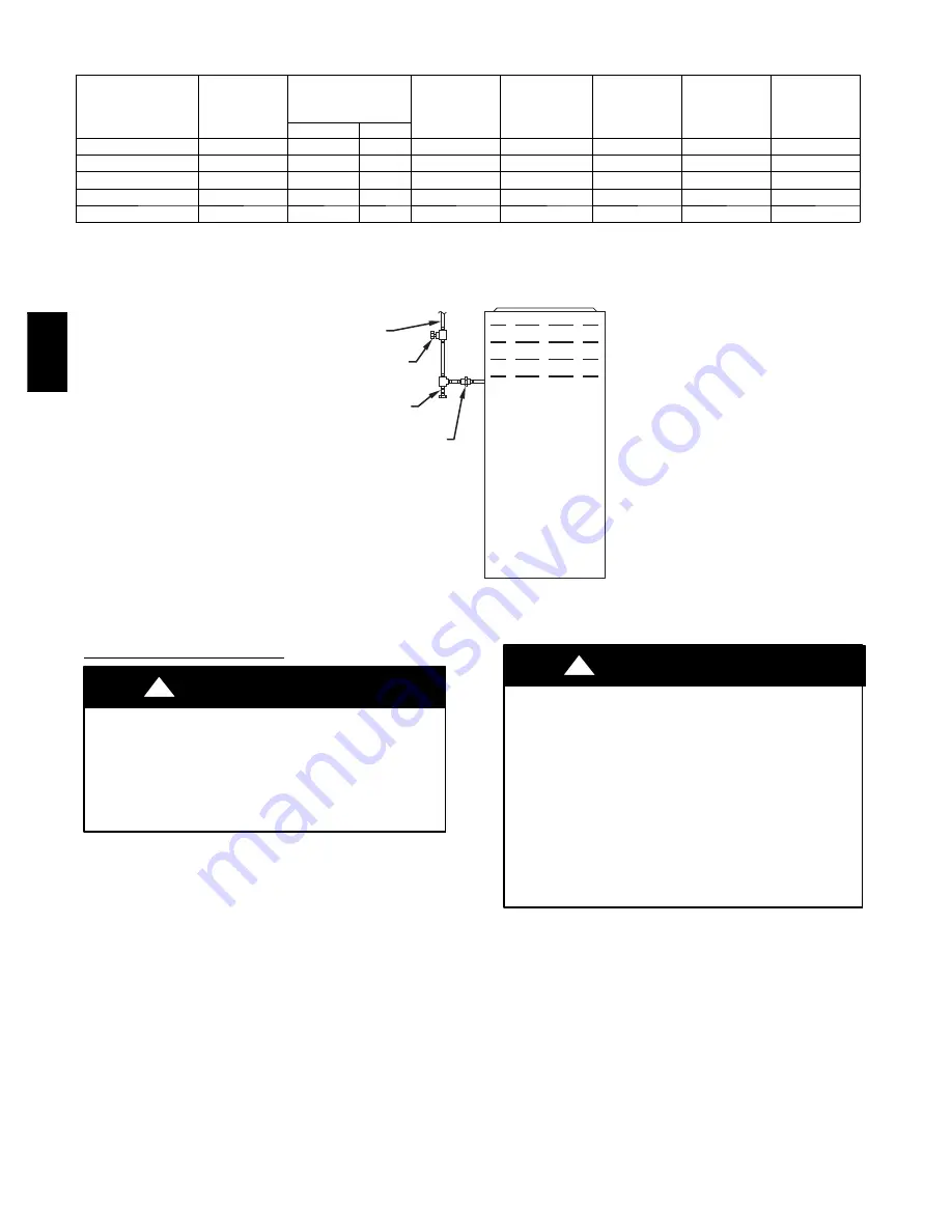
Table 7 – Electrical Data

FURNACE

MODEL

VOLTS---

HERTZ---

PHASE

OPERATING

VOLTAGE*

(VOLTS)

MAX UNIT

(AMPS)

UNIT

AMPACITY#

(AMPS)

MAX WIRE

LENGTH

}

FT. (M)

MAX FUSE/

CKT BKR

{

(AMPS)

MIN WIRE

GAGE

MAX

MIN

045---08 / 024045

115---60---1

127

104

8.1

10.9

34 (10)

15

14

070---16 / 048070

115---60---1

127

104

9.5

12.6

29 (9)

15

14

090---16 / 048090

115---60---1

127

104

10.3

13.4

27 (8)

15

14

110---20 / 060110

115---60---1

127

104

13.1

16.9

34 (10)

20

12

135---20 / 060135

115---60---1

127

104

13.1

16.9

34 (10)

20

12

* Permissible limits of the voltage range at which the unit operates satisfactorily.
# Unit ampacity = 125 percent of largest operating component’s full load amps plus 100 percent of all other potential operating components’ (EAC, humidifier,

etc.) full load amps.

{

Time---delay type is recommended.

}

Length shown is as measured 1 way along wire path between unit and service panel for maximum 2 percent voltage drop.

UNION

SEDIMENT
TRAP

MANUAL
SHUTOFF
VALVE
(REQUIRED)

GAS
SUPPLY

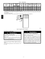
A02035

Fig. 22 -- Typical Gas Pipe Arrangement

ELECTRICAL CONNECTIONS

ELECTRICAL SHOCK HAZARD

Failure to follow this warning could result in personal

injury or death

.

Blower access panel door switch opens 115--v power to

control. No component operation can occur. Do not bypass

or close switch with panel removed.

!

WARNING

See Fig. 25 for field wiring diagram showing typical field 115--v
wiring. Check all factory and field electrical connections for

tightness.
Field--supplied wiring shall conform with the limitations of 63

_

F

(35

_

C) rise.

ELECTRICAL SHOCK AND FIRE HAZARD

Failure to follow this warning could result in personal

injury, death, or property damage.
The cabinet MUST have an uninterrupted or unbroken

ground according to NEC ANSI/NFPA 70--2008 or local

codes to minimize personal injury if an electrical fault

should occur. This may consist of electrical wire, conduit

approved for electrical ground or a listed, grounded power

cord (where permitted by local code) when installed in

accordance with existing electrical codes. Refer to the

power cord manufacturer’s ratings for proper wire gauge.

Do not use gas piping as an electrical ground.

!

WARNING

PG

8M

EA

Summary of Contents for PG8JEA

Page 1: ...36 General 36 Start up Procedures 36 Adjustments 36 Check Safety Controls 39 Checklist 40 SERVICE AND MAINTENANCE PROCEDURES 42 Introduction 42 Electrical Controls and Wiring 42 Care and Maintenance 46 Cleaning and or Replacing Filter 44 Blower Motor and Wheel 44 Cleaning Heat Exchanger 45 Sequence of Operation 46 Wiring Diagrams 48 Troubleshooting 48 Accessory List 52 REPLACEMENT INFORMATION GUID...

Page 2: ...section of these instructions 3 Provide adequate combustion and ventilation air to the furnace space as specified in Air for Combustion and Ventilation section 4 Combustion products must be discharged outdoors Con nect this furnace to an approved vent system only as spe cified in the Venting section of these instructions 5 Never test for gas leaks with an open flame Use a com mercially available s...

Page 3: ...219 219 5 1 2 5 1 2 140 3 140 3 8 7 16 8 7 16 213 5 213 5 FRONT OF CASING FRONT OF CASING TOP OF CASING TOP OF CASING 6 1 6 1 155 7 155 7 2 1 16 2 1 16 51 6 51 6 5 1 5 1 130 5 130 5 1 7 1 7 43 5 43 5 Ø7 8 Ø7 8 22 2 22 2 ACCESSORY 2 ACCESSORY 2 AIR FLOW AIR FLOW AIR FLOW AIR FLOW BOTTOM RETURN BOTTOM RETURN WIDTH WIDTH AIR FLOW AIR FLOW KNOCK OUTS FOR KNOCK OUTS FOR VENTING 5 VENTING 5 PLACES PLACE...

Page 4: ...4 A10269 Fig 2 Clearances to Combustibles PG8MEA ...

Page 5: ...roper installation or service of furnace may cause premature furnace component failure Electrostatic discharge can affect electronic components Follow the Electrostatic Discharge Precautions Procedure listed below during furnace installation and servicing to protect the furnace electronic control Precautions will prevent electrostatic discharges from personnel and hand tools which are held during ...

Page 6: ...low this warning could result in personal injury or death and unit component damage Corrosive or contaminated air may cause failure of parts containing flue gas which could leak into the living space Air for combustion must not be contaminated by halogen compounds which include fluoride chloride bromide and iodide These elements can corrode heat exchangers and shorten furnace life Air contaminants...

Page 7: ...all dust into combustion air which can cause fouling and plugging of furnace components The temperature of the return air to the furnace is maintained between 55_F 13_C and 80_F 27_C with no evening setback or shutdown The use of the furnace while the structure is under construction is deemed to be intermittent operation per our installation instructions The air temperature rise is within the rate...

Page 8: ...eration of either unit unless the damper is in the full heat or full cool position AIR FOR COMBUSTION AND VENTILATION Provisions for adequate combustion ventilation and dilution air must be provided in accordance with S U S installations Section 9 3 of the NFGC NFPA54 ANSI Z223 1 2009 Air for Combustion and Ventilation and applicable provisions of the local building codes WARNING CARBON MONOXIDE P...

Page 9: ...ollow this warning could result in death and or personal injury Many homes require air to be supplied from outdoors for furnace combustion ventilation and dilution of flue gases The furnace combustion air supply must be provided in accordance with this instruction manual WARNING CIRCULATING AIR DUCTS 6 MIN FRONT Ü CIRCULATING AIR DUCTS VENT THROUGH ROOF 1 SQ IN PER 1000 BTUH IN DOOR OR WALL 12 MAX...

Page 10: ...n of Indoor and Outdoor Air 1 Indoor openings shall comply with the Indoor Combus tion Air Method below and 2 Outdoor openings shall be located as required in the Out door Combustion Air Method mentioned previously and 3 Outdoor openings shall be sized as follows a Calculate the Ratio of all Indoor Space volume divided by required volume for Indoor Combustion Air Meth od below b Outdoor opening si...

Page 11: ...commended that the perforated supply air duct flanges be completely folded over or removed from furnace when installing the furnace on a factory supplied cased coil or coil box To remove the supply air duct flange use wide duct pliers or hand seamers to bend flange back and forth until it breaks off Be careful of sharp edges See Fig 14 Bottom Return Air Inlet These furnaces are shipped with bottom...

Page 12: ...ons on combustible flooring KGASB sub base required 15 1 8 384 19 483 16 3 4 425 20 5 8 600 Downflow Applications on Combustible Flooring with CNPV CNRV CAR or CAP Coil Assembly or KCAKC coil box KGASB subbase not required 15 1 2 394 19 483 16 1 2 419 20 508 21 533 Upflow Applications on Combustible or Noncombustible Floor ing KGASB subbase not required 19 1 2 495 21 5 8 549 20 1 8 511 22 1 4 565 ...

Page 13: ...ith bottom closure panel installed in bottom return air opening This panel MUST be in place when side return air inlet s is used without a bottom return air inlet Not all horizontal furnaces are approved for side return air connections See Fig 20 FILTER ARRANGEMENT CARBON MONOXIDE AND POISONING HAZARD Failure to follow this warning could result in personal injury or death Never operate a furnace w...

Page 14: ...ge inward past 90_ with wide duct pliers See Fig 14 The supply air duct must be connected to ONLY the furnace supply outlet or air conditioning coil casing when used When installed on combustible material supply air duct must be connected to ONLY the factory approved accessory subbase or a factory approved air conditioning coil casing DO NOT cut main furnace casing to attach supply side air duct h...

Page 15: ...Suspension with Straps 30 IN 762mm MIN WORK AREA 6 MIN TYPE B VENT 17 3 4 22 SHEET METAL SEDIMENT TRAP EQUIPMENT MANUAL SHUT OFF GAS VALVE LINE CONTACT ONLY PERMISSIBLE BETWEEN LINES FORMED BY INTERSECTIONS OF THE TOP AND TWO SIDES OF THE FURNACE JACKET AND BUILDING JOISTS STUDS OR FRAMING GAS ENTRY 17 3 4 451mm OVERALL 4 3 4 121mm UNDER DOOR 1 25mm UNDER FURNACE EXTEND OUT 12 305mm FROM FACE OF D...

Page 16: ...s control valve and extend a minimum of 2 in 51 mm outside the furnace WARNING Gas piping must be installed in accordance with national and local codes Refer to current edition of NFGC Installations must be made in accordance with all authorities having jurisdiction If possible the gas supply line should be a separate line running directly from meter to furnace NOTE In the state of Massachusetts 1...

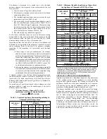
Page 17: ...ormance included 3 4 in 19 mm washable filter media such as contained in factory authorized accessory filter rack To determine airflow performance without this filter assume an additional 0 1 In W C available external static pressure Indicates unstable operating conditions Table 6 Maximum Capacity of Pipe NOMINAL IRON PIPE INTERNAL DIAMETER LENGTH OF PIPE FT M SIZE IN mm In mm 10 20 30 40 50 1 2 1...

Page 18: ...18 A02075 Fig 18 Upflow Return Air Configurations and Restrictions A02163 Fig 19 Downflow Return Air Configurations and Restrictions PG8MEA ...

Page 19: ...19 A02162 Fig 20 Horizontal Return Air Configurations and Restrictions 2 51mm Street Elbow A08551 Fig 21 Burner and Manifold PG8MEA ...

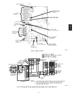
Page 20: ...l Gas Pipe Arrangement ELECTRICAL CONNECTIONS ELECTRICAL SHOCK HAZARD Failure to follow this warning could result in personal injury or death Blower access panel door switch opens 115 v power to control No component operation can occur Do not bypass or close switch with panel removed WARNING See Fig 25 for field wiring diagram showing typical field 115 v wiring Check all factory and field electric...

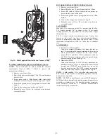
Page 21: ...r to move the J Box Do NOT remove green ground screw inside J Box 2 Cut wire tie on loop in furnace wires attached to J box 3 Move J Box to desired location 4 Fasten J Box to casing with two screws removed in Step 1 5 Route J Box wires within furnace away from sharp edges rotating parts and hot surfaces ELECTRICAL CONNECTION TO J BOX Electrical Box on Furnace Casing Side FIRE OR ELECTRICAL SHOCK H...

Page 22: ...r proper cooling operation Use only AWG No 18 color coded copper thermostat wire The 24 v circuit contains an automotive type 3 amp fuse located on the control Any direct shorts during installation service or maintenance could cause this fuse to blow If fuse replacement is required use ONLY a 3 amp fuse of identical size ACCESSORIES 1 Electronic Air Cleaner EAC Connect an accessory Electronic Air ...

Page 23: ...AUXILIARY J BOX 24 V TERMINAL BLOCK THREE WIRE HEATING ONLY FIVE WIRE NOTE 1 NOTE 2 FIELD SUPPLIED DISCONNECT CONDENSING UNIT TWO WIRE FURNACE C O N T R O L R G COM W C R G Y GND GND FIELD 24 V WIRING FIELD 115 208 230 460 V WIRING FACTORY 24 V WIRING FACTORY 115 V WIRING 208 230 OR 460 V THREE PHASE 208 230 V SINGLE PHASE BLOWER DOOR SWITCH WHT BLK WHT BLK NOTES Connect Y terminal in furnace as s...

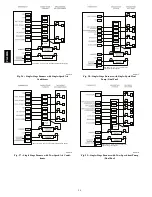
Page 24: ...wing these figures A04216 Fig 27 Single Stage Furnace with Two Speed Air Condi tioner See notes 1 2 4 6 7 9 10 and 12 on the page following these figures A04217 Fig 28 Single Stage Furnace with Single Speed Heat Pump Dual Fuel See notes 1 2 3 4 6 8 9 10 and 12 on the page following these figures A04218 Fig 29 Single Stage Furnace with Two Speed heat Pump Dual Fuel PG8MEA ...

Page 25: ...default 5 Dip switch No 1 on humidity sensing thermostat should be set in ON position for heat pump installations 6 Dip switch No 2 on humidity sensing thermostat should be set in OFF position for single speed compressor operation This is factory default 7 Dip switch No 2 on humidity sensing thermostat should be set in ON position for two speed compressor operation 8 Configuration Option No 10 Dua...

Page 26: ...nd installation requirements including local building codes the National Fuel Gas Code ANSI Z223 1 2009 NFPA 54 2009 NFGC Parts 12 and 13 the local building codes and furnace and vent manufacturers instructions These furnaces are design certified as Category I furnaces in accordance with ANSI Z21 47 2006 CSA 2 3 2006 and operate with a non positive vent static pressure to minimize the potential fo...

Page 27: ...nry Chimney FAN NAT Installations with Type B Double Wall Vent Connectors NFPA AGA Table 8 Combined Appliance Maximum Input Rating in Thousands of BTUH per Hour VENT HEIGHT FT M INTERNAL AREA OF CHIMNEY IN2 MM2 12 7741 19 12258 28 18064 38 24516 6 1 8 74 119 178 257 8 2 4 80 130 193 279 10 3 0 84 138 207 299 15 4 5 NR 152 233 334 20 6 0 NR NR 250 368 30 9 1 NR NR NR 404 Table 9 Minimum Allowable I...

Page 28: ...28 A10133 Fig 33 Chimney Inspection Chart PG8MEA ...

Page 29: ... factory supplied vent elbow does NOT count as part of the number of vent connector elbows The vent connector can exit the furnace through one of 5 locations on the casing 1 Attach the single wall vent connector to the furnace vent elbow and fasten the vent connector to the vent elbow with at least two field supplied corrosion resistant sheet metal screws located 180_ apart NOTE An accessory flue ...

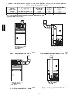
Page 30: ...ig 42 132 000 5 127 7 2 NOTE All vent configurations must also meet National Fuel Gas Code venting requirements NFGC 4 in 102 mm inside casing or vent guard Including 4 in 102 mm vent section s SEE NOTES 1 2 4 7 8 9 on the page following these figures A03208 Fig 34 Upflow Application Vent Elbow Up SEE NOTES 1 2 3 4 7 8 9 on the pages following these figures A03209 Fig 35 Upflow Application Vent El...

Page 31: ... 9 on the page following these figures A03212 Fig 39 Downflow Application Vent Elbow Up then Right SEE NOTES 1 2 4 7 8 9 on the page following these figures A03213 Fig 40 Horizontal Left Application Vent Elbow Left SEE NOTES 1 2 4 5 7 8 9 on the page following these figures A03214 Fig 41 Horizontal Left Application Vent Elbow Right then Up PG8MEA ...

Page 32: ...nstallations must use Type B vent immediately after exiting the furnace except when factory authorized Downflow Vent Guard Kit is used in the downflow position See Table 16 for accessory listing 4 Type B vent where required refer to Note 1 above 5 Four inch single wall 26 ga min vent must be used inside furnace casing and when the Downflow Vent Guard Kit is used external to the furnace See Table 1...

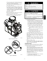
Page 33: ...LECTRICAL SHOCK HAZARD Failure to follow this warning could result in personal injury or death Blower access door switch opens 115 v power to control No component operation can occur unless switch is closed Caution must be taken when manually closing this switch for service purposes WARNING NOTE The furnace control allows all components except the gas valve to be run for short period of time This ...

Page 34: ...and turn regulator adjusting screw counterclockwise out to decrease input rate of clockwise in to increase input rate h Install regulator seal cap i Leave manometer or similar device connected and pro ceed to Step 4 NOTE DO NOT set manifold pressure less than 3 2 In W C or more than 3 8 In W C for natural gas at sea level If manifold pressure is outside this range change main burner orifices Refer...

Page 35: ...W The thermostat anticipator should NOT be in the circuit while measuring current 1 Remove thermostat from subbase or from wall 2 Connect an amp meter as shown in Fig 49 across the R and W subbase terminals or R and W wires at wall 3 Record amp draw across terminals when furnace is in heating and after blower starts 4 Set heat anticipator on thermostat per thermostat in structions and install on s...

Page 36: ...eck draft safeguard switch The purpose of this control is to cause the safe shutdown of the furnace during certain blocked vent conditions R Y W G 10 TURNS THERMOSTAT SUBBASE TERMINALS WITH THERMOSTAT REMOVED ANITICIPATOR CLOCK ETC MUST BE OUT OF CIRCUIT HOOK AROUND AMMETER EXAMPLE 5 0 AMPS ON AMMETER 10 TURNS AROUND JAWS 0 5 AMPS FOR THERMOSTAT ANTICIPATOR SETTING FROM UNIT 24 V CONTROL TERMINALS...

Page 37: ... 621 78 46 92 231 30 120 240 600 80 45 90 225 31 116 232 581 82 44 88 220 32 113 225 563 84 43 86 214 33 109 218 545 86 42 84 209 34 106 212 529 88 41 82 205 35 103 206 514 90 40 80 200 36 100 200 500 92 39 78 196 37 97 195 486 94 38 76 192 38 95 189 474 96 38 75 188 39 92 185 462 98 37 74 184 40 90 180 450 100 36 72 180 41 88 176 439 102 35 71 178 42 86 172 429 104 35 69 173 43 84 167 419 106 34 ...

Page 38: ...38 Table 13 Orifice Size and Manifold Pressure In W C for Gas Input Rate A10180 PG8MEA ...

Page 39: ...39 Table 13 Orifice Size and Manifold Pressure In W C for Gas Input Rate CONT A10180A PG8MEA ...

Page 40: ...40 Table 14 Orifice Size And Manifold Pressure In W C For Gas Input Rate A10181 PG8MEA ...

Page 41: ...41 Table 14 Orifice Size And Manifold Pressure In W C For Gas Input Rate CONT A10181A PG8MEA ...

Page 42: ...or field wiring information and to Fig 54 for furnace wiring information NOTE If the polarity is not correct the STATUS LED on the control will flash rapidly and prevent the furnace from heating The control system also requires an earth ground for proper operation of the control and flame sensing electrode The 24 v circuit contains an automotive type 3 amp fuse located on the control See Fig 24 An...

Page 43: ...out Switch open 34 IGNITION PROVING FAILURE Control will try three more times before lockout 14 occurs If flame signal lost during blower on delay period blower will come on for the selected blower off delay Check for Flame sensor must not be grounded Oxide buildup on flame sensor clean with fine steel wool Proper flame sense microamps 5 microamps D C min 4 0 6 0 nominal Gas valve defective or gas...

Page 44: ...motor and wheel as follows 1 Turn off electrical supply to furnace 2 Remove outer door 3 For downflow or horizontal furnaces having vent pipes within the furnace that pass in front of the blower access door a Disconnect vent connector from furnace vent elbow b Disconnect and remove short piece of vent pipe from within furnace 4 Remove two screws from blower access door and remove blower access doo...

Page 45: ...avy build up of soot and carbon indicates that a problem exists which needs to be corrected such as improper adjustment of manifold pressure insufficient or poor quality combustion air incorrect size or damaged manifold orifice s improper gas or a restricted heat exchanger Action must be taken to correct the problem If it becomes necessary to clean the heat exchangers because of dust or corrosion ...

Page 46: ...and check furnace for proper operation 18 Verify blower airflow and speed changes between heating and cooling 19 Check for gas leaks 20 Replace outer access door A91252 Fig 53 Cleaning Heat Exchanger Cell FIRE OR EXPLOSION HAZARD Failure to follow this warning could result in personal injury death and or property damage Never purge a gas line into a combustion chamber Never test for gas leaks with...

Page 47: ...ill remain energized for an additional 90 seconds Jumper Y1 to DHUM to re duce the cooling off delay to 5 seconds See Fig 24 3 Humidity Sensing Thermostat Mode See Fig 26 29 for humidity sensing thermostat connec tions The dehumidification output DHUM on the humidity sensing thermostat should be connected to the furnace control thermostat terminal DHUM When there is a dehu midify demand the DHUM i...

Page 48: ...e same time the blower motor BLWM will remain on for the selected blower OFF delay period If the R to W and Y1 signals disappear leaving the G signal the blower motor BLWM will remain on for the selected blower OFF delay period then switch to continuous blower speed When the R to W and Y Y2 R to W and Y Y2 and G R to W and Y1 and Y Y2 or R to W and Y1 and Y Y2 and G circuits are ener gized the fur...

Page 49: ...49 A08176 Fig 54 Wiring Diagram PG8MEA ...
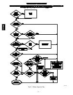
Page 50: ...t sequence The inducer will start and run for the entire component test The HSI blower motor FAN speed AMBER LED boards only HEAT speed and COOL speed will run for 10 15 seconds each Gas valve and humidifier will not be turned on Was there a previous status code other than 11 Is door switch closed Is there 115V going to switch Replace door switch Replace transformer Does the control respond to W Y...

Page 51: ...tion air supply flame rollout switch open Restricted vent Proper vent sizing Excessive wind 34 IGNITION PROVING FAILURE If flame is not sensed during the trial for ignition period the control will repeat the ignition sequence 3 more times before lockout 14 occurs If flame signal is lost during the blower on delay period blower will come on for the selected blower off delay Check the following item...

Page 52: ...ter Rack KGAFR0801SRE Ext Side filter rack all casings includes filter Unframed Filter 3 4 in 19 mm KGAWF1301UFR 1 unframed filter 16x25x3 4 406x635x19 mm KGAWF1401UFR 1 unframed filter 20x25x3 4 508x635x19 mm KGAWF1501UFR 1 unframed filter 24x25x3 4 610x635x19 mm KGAWF1306UFR 6 unframed filter 16x25x3 4 406x635x19 mm KGAWF1406UFR 6 unframed filter 20x25x3 4 508x635x19 mm KGAWF1506UFR 6 unframed f...

Page 53: ...RMATION ON PARTS Consult your installing dealer or classified section of your local telephone directory under Heating Equipment or Air Conditioning Contractors and Systems headings for dealer listing by brand name or contact PAYNE HEATING COOLING Consumer Relations Department P O Box 4952 Syracuse New York 13221 4952 1 800 417 2963 Have available the model number series number and serial number lo...

Page 54: ...0 W Morris St S Indianapolis IN 46206 Manufacturer reserves the right to change at any time specifications and designs without notice and without obligations Catalog No IM PG8MEA 03 Replaces IM PG8MEA 02 Printed in U S A Edition Date 08 10 PG8MEA ...
Reviews: