background image

56


IMPORTANT 

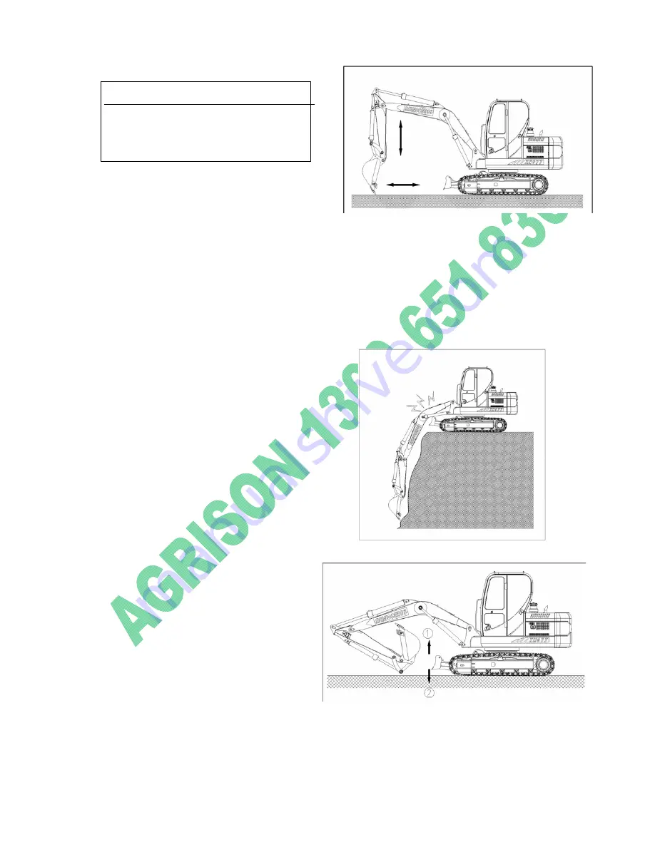
Do  not  overuse  the  bucket  to  lev

ground;  otherwise  some  parts  wi

el

ll

Level  ground 


break due to overload working. 


1 . Using  the  dozer  plate  to  level 

ground. 

2. Using the boom, bucket arm and 

bucket. 

A.  When level the ground from front to back, raise the boom, at the same 

time slowly move the bucket arm, when the bucket arm is near the machine, 

stably lower the boom to let the bucket move horizontally. 

B.Do in the reverse order when level ground from back to front. 


Pay attention to the position 
of dozer plate
 

1.The dozer plate may touch the boom 

cylinder  and  the  bucket  when  it  is 

forward, be careful. 

2.Keep the dozer plate backward when 

digs deeply. 


1

the dozer plate is to bulldoze, not for 

digging, otherwise it will hurt the 

dozer plate and the hydraulics. 

2.The dozer plate can not stand 

heavy thing 

3.Do not let the dozer plate hookup 

any thing when walks. 

4.Be sure the ground is even and 

solid when using it to support 

the excavator. 

Fig 3-60 

https://tractormanualz.com

Summary of Contents for ME8000

Page 1: ...ME80 O Ope 000 Excavator ti g M l erating Manual https tractormanualz com ...

Page 2: ...uilding architecture water supply gas supply docks and goods yards Please take notice that we can not honor any claims which could arise due to careless handling improper operation inadequate maintenance use of unauthorized oils or lubricants non observance of the safety instructions etc We reserves the rights to cancel any warranty claims service contracts etc without prior notice if any other th...

Page 3: ...afety guideline for cabin 13 Signs on the hydraulic excavator 13 Ⅲ OPERATION AND CONTROL Parts position 15 Cab 16 Instrument panel 21 Keyset 24 AC system 26 Sound system 28 Seat adjustment 29 Front window 30 Grinding in new machine 32 Starting and stopping 33 Walking 44 Operating instructions 50 Ⅳ LUBRICATION General safety information 59 Lubricant and fuel specifications 60 Checking coolant level...

Page 4: ...screws for tightness 69 Hydraulic system 69 The electrical system 70 The swing and travel brake 71 Adjusting the clearance of the bucket 72 Replacing wear and tear items 72 Maintenance schedule 72 Ⅵ TROUBLE ANALYSIS GUIDELINE Engine trouble 76 Trouble of electrical system 76 Others 77 https tractormanualz com ...

Page 5: ...n motor Low speed 2 9 km h High Speed 3 2km h Travel brake hydraulic disc brake Parking brake Oil release No of track shoes 2x43 Travel speed 2 9 4 2 Km h Grade ability 30 nd clearance 260mm Hydraulic system Hydraulic pump Imported from Korea Type Axial Plunger Pump gear pump Max discharge flow 2x79 L min Pilot control pump Gear pump Main control valves Negative flow control system Oil cooler Air ...

Page 6: ...hics ABS PVC plastic Technology inside it smooth lines of the outer surface sturdy and durable Way of control Two hand levers and two foot pedals for travel Throttle hand control Boom Arm Bucket Boom cylinder 80 50 750X1060 mm Stick cylinder 100 63 880X1240 mm Bucket cylinder 90 50 600X925 mm Bulldozing Cylinder 105 60 193X536 mm Refilling capacity lubrications Main Pressure P1 P2 P3 28 Mpa 28 Mpa...

Page 7: ...Metal Tensioning control type Grease Overall width 2090mm Ground pressure 0 37Kgf cm2 Operating weight 7500Kg Dimension and working range Length 6400 mm Width 2090 mm Height 2690 mm Dozer Blade Wide Length 2030x390 mm Height of max clearing range 320 mm Working Range Boom Length 3330 mm Bucket Arm Length 2000 mm Max excavating range 6430 mm Max excavating depth 3850 mm Max excavating height 5950 m...

Page 8: ...4 Normal operating range https tractormanualz com ...

Page 9: ...WARNING denotes a reminder of safety practices or directs attention to unsafe practices if proper precautions are not taken NOTICE describes operation and maintenance procedures which should be followed to keep your excavator operation and to insure long machine life and or to facilitate certain procedures DESTINED USE Destined use is considered part of observing and adhering to all regulations an...

Page 10: ...n or off the excavator Never use the steering column control lever or joysticks as handholds Never jump off the excavator climb on or off the excavator using only the steps rails and handles provided When climbing on or off the excavator use both hands for support and face the machine If needed use the front window as an escape hatch If no other guidelines are given perform maintenance and repairs...

Page 11: ...n be under pressure Always wear safety glasses and protective gloves when handling batteries Keep sparks or open flames away Never permit anyone to hand guide the bucket or grapple into position When working in the engine area make sure the top covers and side doors are properly secured or closed with the appropriate supports FIRE AND EXPLOSION PREVENTION Always turn off the engine while refueling...

Page 12: ... lever up Before starting the engine alert any nearby personnel that the excavator is being started by sounding the horn Start the machine only when seated in the operator s seat and with the seat belt fastened if installed If you have no other instructions start the engine as outlined in the Operation and Maintenance Manual Tilt the safety lever down and check all indicators gauges warning device...

Page 13: ...onnel on the excavator Report any problems or needs repairs to your foreman or supervisor and make sure they are correctedimmediately Do not move the excavator until you are certain that surrounding area is safe On machines without negative brakes check the brake system before starting to work as outlined in the Operation Maintenance Manual Never leave the operator s seat while the machines are st...

Page 14: ...e machine on a flatbed trailer or railroad car be sure that the loading ramp incline is less than 30º and covered with wooden planks to prevent skidding Remove all mud snow or ice from track components before moving up the ramp Before loading secure the upper carriage with the under carriage with the lock pin Align the machine with the loading ramp Attach the manual control levers to the foot peda...

Page 15: ...ot be made unsafe when performing maintenance work Never attempt maintenance procedures or repairs you do not understand Check the Operation Maintenance Manual for service and maintenance intervals Make sure you use only appropriate tools for all maintenance work During maintenance do not allow unauthorized personnel to enter the maintenance are Before any maintenance work and especially when work...

Page 16: ...chains with wedges and secure the upper carriage to the undercarriage with the lock pin Never loosen or remove lines or fitting before the working device has been lowered to the ground and the engine has been turned off Then turn the ignition key to contact position move all servo controls hand control lever and foot pedals in both direction to release pressures Then release the tank pressure as o...

Page 17: ...hold on to the machine at three points As soon as you can reach the handle of the door with your free hand unlock and open the door before climbing up any more Keep and guide the doors all the way with your hand and lock it in its opened position making sure it is securely fixed in this position so it can not be slammed by the wind Some external influences and especially the wind may make the open...

Page 18: ...r Cautions before operating the Excavator 6 Warning Sign on Water tank To avoid being scalded 7 Safety Warning Cautions when the Engine turning on 8 No Entering Warning Entering into the swing area is strictly prohibited Caution 1 Turn off the Engine before open the cover 2 Don t open the cover when the oil temperature is high 3 Open the cover slowly to release the inner pressure 4 Don t loose the...

Page 19: ...ent panel 4 Appliance board 5 Air conditioner system 6 Sound system 7 Adjustment of seat 8 Safe belt 9 Front glass 10 Control bar of door 11 Inside lights of the cab WARNING Warning light buzzer or each lights on the appliance board go on or sound worn please cut off the power clear the faults https tractormanualz com ...

Page 20: ...d 7 connecting rod 8 bucket 9 swing platform 10 engine hook 11 fuel tank 12 hydraulic oil tank 13 cab 14 balance weight 15 dozer blade 16 dozer blade cylinder 17 guide pulley 18 idler strain spring 19 thrust wheel 20 traveling motor 21 radiator 22 engine 23 crawler belt https tractormanualz com ...

Page 21: ...t panel 5 left joystick 9 travelling bar 13 radio 2 starting switch 6 right joystick 1O trabelling bar 3 horn switch 7 manual accelerator 11 safe bar 4 AC control panel 8 dozer blade joystick 12 buttons https tractormanualz com ...

Page 22: ...e lights on B off position turn to this position the engine flameout electric system power off C switch on position turns to this position engine on Fig 2 3 Fig 2 4 WARNING Starting switch is with the function of preventing the engine restart when the machine works the switch must be turn to off position when the engine is started again next time https tractormanualz com ...

Page 23: ...compressor stop b blowing rate switch Fig 2 6 left switch blowing rate switch is to control the blowing rate there are three grades O position fan stop position L low blowing rate position M middle blowing rate position H high blowing rate 5 Left joystick with hydraulic hammer switch To control the machine swing and bucket arm movement 6 Right joystick with horn switch Fig 2 5 https tractormanualz...

Page 24: ...d B high speed Fig 2 9 8 Joystick of dozer plate It is on the right side of the seat A draw back the joystick raise the joystick B push the joystick lower the joystick Fig 2 10 9 and 10 Traveling joystick These two joysticks control the forward and back of the machine 11 Safety pole The safety pole is to lock the joystick when the machine travel Fig 2一l2 https tractormanualz com ...

Page 25: ...21 12 Radio Refer to the sound https tractormanualz com ...

Page 26: ...ndicate when temperature is from 40 106 it indicate the green area when temperature is above 106 it indicate the red area and the buzzer sound press the mute button the buzzer stop sound 2 Fuel level indicator the LCD blue area indicate when the fuel tank oil level is above 10 of the oil tank it indicate the green area When the fuel level is below 10 of the fuel tank it indicate the LCD red area a...

Page 27: ...nd press the button now the mute indicator light buzzer stop sound Working head lights Windshield wiper Walking speed 5 Working head lights press the button the indicator lights light the head lights work now if the indicator light out the head lights out too 6 Windshield wiper press the button if the windshield wiper indicate the high speed now the wiper is on high speed press again the button th...

Page 28: ...ghts now the machine are traveling in low speed WARNING If the front glass is dry please first spray water then use the windshield unless it may break the glass or the wiper When there is some sand or dirt on the glass please clean the glass first then use the windshield unless it may break the glass or the wiper https tractormanualz com ...

Page 29: ...y 7 Fuse block 1 Alarm relay when the electric switch is on the alarm relay is connected and output control signal When the alarm relay makes sound the electric system has faults now the machine should be stop and checked and clear the faults 2 keyset it is used to install the relays and fuse block https tractormanualz com ...

Page 30: ...ol the starting motor on the engine when the starting switch is on ON position starting compound relay supply power to motor to start the motor At the same time it collects all the signals from generator to make sure every parts work well 5 Horn relay 6 Head light relay to control the on and off of the head lights 7 Fuse block it consists of all the fuses of this machine all the power are outputte...

Page 31: ... 17 rotate the air outlet direction accordingly to get proper outlet direction Fig 2 16 turn the wind speed switch anticlockwise to O position the AC turn off now Refrigeration elementary operation Choose the proper wind speed and direction according to ventilation elementary operation Fig2 16 turn the AC switches clockwise to proper position turn clockwise Refrigeration effect stronger Regulate t...

Page 32: ...28 Fig 2 16 turn the AC switch anticlockwise to O position then turn the wind speed switch to O position to shut down the AC https tractormanualz com ...

Page 33: ...29 Sound system Fig 2 18 1 Controller and switch ON OFF volume pause play random digital LCD function switch sound mode former next FM AM USB https tractormanualz com ...

Page 34: ...and back adjustment Move the adjusting rod to adjust the proper position left right adjustment range 160mm Seat adjustment Lift the adjusting rod on the left of the seat to get the ideal height Fig 2 19 https tractormanualz com ...

Page 35: ...Fig 2 22 2 Loosen the both side locking pin of the window on the top the cab Fig 2 23 3 Lifting the window and lock on the top of the cab by using these two handles 4 Screw up the two locking pins to make sure its safe Fig 2 24 NOTE reverse the procedures to install the window Fig 2 23 Fig 2 24 https tractormanualz com ...

Page 36: ...32 Action bar of open and close door Push the action bar as the indicated direction to open the lock Fig 2 25 Interior lamp in the cab Press the switch the lamps works Fig 2 26 https tractormanualz com ...

Page 37: ...he rated speed when the machine is grinding in 1 5 The following inspections should be carried after the 8 hours grinding in 1 5 1 Check if there is some noise or over heated of each transmission parts 1 5 2 Check the tightness of air fan belt 1 5 3 Check the oil level of transmission box 1 5 4 Check the tightness of oil pipes of hydraulic system and braking system 1 5 5 Check the connection fixed...

Page 38: ...ccording to the working hour gauge 5 safe check around the machine makes sure there is no person under the machine then starts to maintain 6 Check all action bars and other parts Checking before starting 1 safe bar is on the lock position Fig 3 1 Fig 3 1 WARNING Please put the safe bar on the lock position before leave the machine WARNING If there are combustibles such as paper and leaves on the h...

Page 39: ...harging warning light fuel gauge engine oil pressure warning light NOTE If all the lights do not work when power on there must be somewhere wrong The buzzer will warn for 2 seconds Engine starting Fig 3 2 Fig 3 3 1 Check according to the procedures of engine before starting 2 Put the accelerator handle on the level of a little higher than the idle speed 3 Sound horn Fig 3 4 WARNING Sound horn befo...

Page 40: ...ch back to off position start again after 5m 4 The engine should be started in 5s after turn the switch to start position Fig 3 5 5 The key will go back to start position automatically after the engine is started and loosen the key Fig 3 7 https tractormanualz com ...

Page 41: ...ning indicator light no Air filter warning indicator light no 8 Purging system checking no color or blue engine works well black combustion insufficiency check reason white or deep blue burning engine oil check reason Check engine vibration and noise if there is noise and vibration check the reason Starting on low temperature WARNING When using preheating system does not use starting fluid it may ...

Page 42: ... Do not connect the earth wire of the auxiliary boost battery to the engine battery directly find a connecting position on the machine 4 The battery may produce hydrogen when discharged it may cause explosive 5 Pull up the machine on a dry area or on concrete ground and then start the engine Do not start on steel plade https tractormanualz com ...

Page 43: ...directly 3 start the engine as instructed 4 After the engine is started move the boost Wire from negative to positive pole Fig 3 11 1 Running the engine in middle speed for 5m without loading Preheating of hydraulic system Stop the engine at once if there are some faults or misoperating make sure the excavator reach normal temperature before working especially in low temperature environment the no...

Page 44: ...ise for 3 cycles then anticlockwise for 3 times 5 Put the working device on ground to Let one side of the track shoe off ground On a firm ground the other side track Shoe on ground control the traveling Motor forward and backward for two times then check the other side track shoe in the same way Warming up of the hydraulic system in low temperature 1 Running the engine in idle speed without load f...

Page 45: ...for 5 times to cycle The hydraulic oil in the hydraulic system For 5 minutes NOTE do not let the cylinder to reach Two dead point 5 Put the accelerator operating bar on The high speed position Fig 3 20 6 Repeat the procedures of 3 for 5 minutes Again if the working temperature is still Low keep operating but be careful 7 Check the interval by lifting the working devices Fig 3 19 Fig 3 20 https tra...

Page 46: ...oe in the same way Stop the engine NOTE running the engine idly for 3 5minutes before shop the engine unless the heat may cause problem to the engine 1 Park the excavator on level and firm ground 2 Put the working device on ground 3 Put the accelerator operating bar on The lowest speed position Fig 3 22 then Running the engine for 3 5minutes in Idle position 4 Turn the key to off position Fig 3 23...

Page 47: ...p 1 If the excavator oil or coolant liquid leak check and repair 2 Check the working devices and under part 3 Refilling fuel 4 Clear the combustibles around the engine such as leaf paper and so on 5 Clean the sludge on the under parts and track shoe make sure all the paddles and cab are clear and clean https tractormanualz com ...

Page 48: ...do not work Fig 3 24 2 Pull down the safety pole to unlock position before starting to work NOTE when the engine is not running safety pole on unlock position starting key on ON position operating the handle the machine can work Accumulator can supply the pressure to control the valve element Fig 3 25 WARNING Be sure to lock the safety pole after stop the machine and leave the cab unless may cause...

Page 49: ... walking make sure there is no person on or around the machine sound horn to warn that the machine is starting 3 Operate the machine traveling rod slowly and smoothly do not start or stop suddenly 4 Lock the controlling system before leaving the machine stop the engine in case of some accident Walking overview 1 set the accelerator according to the excavator speed Fig 3 26 Fig 3 26 2 put safety ro...

Page 50: ...re make sure it is safe the machine may turn over swing the excavator with load on slope is very dangerous if it is inevitable first fill up and make even 3 Draw back the working device to let it off ground Fig 3 28 4 make sure the bucket off ground completely Fig 3 28 6 When walks on uneven ground choose low speed 1 0 1 5km h to reduce the speed of the engine Fig 3 29 7 Walking slowly on irregula...

Page 51: ...ust or sands on the track shoe lift the two track shoes and turn so to clear it To let the excavator works on even ground as far as possible Fig3 30 WARNING If to support any part of the excavator by boom or arm swing the bucket to make sure the under part of the bucket touch ground and the angle between boom and arm should be 90 degree https tractormanualz com ...

Page 52: ...se series damage to the machine Make sure the sludge is cleared Fig3 32 and Fig 3 33 Fig 3 33 10 When going straight Fig 3 34 push forward or pull backward the operating rod pedal The movement of the operating rod pedal bigger the faster of the machine will be Fig 3 34 11 If only control one operating rod forward or backward the excavator will circle around the still track shoe Fig 3 35 Fig 3 35 h...

Page 53: ...the center position the machine will brake automatically and parked Action bar ISO Fig 3 36 Fig 3 37 warning Please check around the machine before swinging the machine The structure of action bar on this excavator meet to the criterion of ISO do not change the valve and pipes casually There are indicator drop on the right side of cab Fig3 38 Fig 3 38 https tractormanualz com ...

Page 54: ... the middle position or the engine is stop the excavator will swing brakeautomatically NOTE the following phenomenon are normal it is not the excavator s problem The bucket arm may hesitate when working when the bucket arm works the oil supply may not sufficient due to the fast movement of the bucket arm caused by it weight Fig 3 39 Fig 3 40 Right operating rod Fig 3 4l and Fig 3 42 boom down boom...

Page 55: ...eck the hardness of working area If it is not solid enough first reinforce before working 4 The boom bucket arm or the bucket may touch the machine body in some working environment 5 Do not continuously full stretch out the cylinder it may cause problem to the machine FIG 3 44 Fig 3 45 WARNING When operating the machine work do not put your feet on the walking operating rod the machine may move su...

Page 56: ... weight Fig 3 47 8 When works on soft earth or muddy ground be careful the sink of the machine 9 When works by the road or near the cliff Keep the solid of the earth in some case do not work lonely keep the traveling motor on the rear part of the machine Fig 3 48 10 Do not dig the under of the machine Fig 3 49 Fig 3 46 Fig 3 48 Fig 3 49 https tractormanualz com ...

Page 57: ...o not crash the roof and keep good ventilation Fig 3 51 13 Do not use the bucket as a hammer or a pile driver it is dangerous will cause serious problem to the machine Fig 3 52 14 When the track shoes is off ground do not digging anymore otherwise may brake some parts of the machine Fig 3 53 Fig3 51 Fig 3 53 Fig 3 52 https tractormanualz com ...

Page 58: ...instructions should be applied problem to the inner parts Working under water WARNING The gradient of the machine can not exceed 15 degree when work in water otherwise the radiator or the fan maybe broken WARNING Do not raise the working device when go downhill do not traverse the slope go straight when do uphill or downhill be careful when swing the excavator on slope there must be enough swing c...

Page 59: ...lid and dry area check carefully clear all problems then work again Working on poor holding capacity ground 1 Try to avoid working on poor holding capacity ground 2 Try to let the track shoes touch the ground fully do not let the track shoes sink in the earth too depth otherwise can not be pulled out Fig 3 57 4 If the machine stop walking the ground is good then it can be trailed by rope Refer to ...

Page 60: ...t move horizontally B Do in the reverse order when level ground from back to front Pay attention to the position of dozer plate 1 The dozer plate may touch the boom cylinder and the bucket when it is forward be careful 2 Keep the dozer plate backward when digs deeply 1 the dozer plate is to bulldoze not for digging otherwise it will hurt the dozer plate and the hydraulics 2 The dozer plate can not...

Page 61: ...front working device do not let the bucket touch the dozer plate Be careful do not let the dozer plate Touch anything 1 do not let the dozer plate touch anything otherwise the dozer plate cylinder or other parts may be broken Fig 3 62 Fig 3 63 Fig 3 64 https tractormanualz com ...

Page 62: ...58 Packing of excavator Fig 3 70 1 Park the excavator on a solid even ground lower the bucket and dozer plate Fig 3 71 https tractormanualz com ...

Page 63: ... rod Fig 3 72 on the idle position run the machine For 3 5 minutes Fig 3 72 3 Turn the key to OFF position shut down the engine Fig 3 73 4 Pull out the key Fig 3 73 5 Put the safety rod Fig 3 74 on the lock position Fig 3 74 https tractormanualz com ...

Page 64: ...n working in the engine area make sure the covers and side doors are secured Only add fuel when the engine is turned off Never smoke or allow an open flame in refueling area Cleanliness is very important when changing engine gear or hydraulic oil Before removing fittings or plugs make sure the surrounding areas are cleaned When changing the oil clean the fill or drain plugs IMPORTANT Be sure to dr...

Page 65: ...uid denatured alcohol 5 0 L Fuel Use only fuel with a sulfur content of less than 0 5 and not less than the requirement of GB252 94 115L Diesel Engine 16 4L Anti freeze The max anti freeze temperature of antifreeze 22 5L Hydraulic system In hydraulic tank 120 L In hydraulic system 240 L SAE Society of Automotive Engineers API American Petroleum Institute https tractormanualz com ...

Page 66: ...tion oil fuel and coolant please see the Operation Maintenance Manual for Engine CHECKING THE COOLANT LEVEL When the cool ant is cold the coolant level should be no lower the Low line To check the coolant level only after the cap of expansion reservoir is cool enough to touch Turn the cap of expansion reservoir slowly to relieve pressure To add the proper antifreeze mixture to the cooling system o...

Page 67: ...ant also has to be drained from the cooling pump TOADD THE COOLANTAND VENT THE COOLING CIRCUIT Reinstall the cover of the drain valve close the plug and add the coolant to the expansion tank through the filler neck Start the engine run it in low idle for about 30 seconds Turn the engine off and add more coolant into the expansion tank up to the required marks IMPORTANT When adding coolant make sur...

Page 68: ...ed under hard conditions or in multi shift service lubricate more often up to once a day LUBRICATION OFATTACHMENT BEARING POINTS The main lubrication points are as follow Cylinders and boom stick bucket connection connection between boom and upper carriage Every lubrication point should be added sufficient grease To lubricate the attachment add grease on every grease fitting until clean grease run...

Page 69: ...ry time when the hydraulic oil is changed every 500 working hours CHECK THE HYDRAULIC OIL LEVEL When checking the oil level park the machine on the level ground put down the boom stick and rest the bucket on the ground with stick and tilt cylinders fully extended In this position the oil level must not drop below the middle level on the sight gauge or oil must be added to the tank until reaching t...

Page 70: ... via the opening of the breather valve 2 until the oil level reaches the middle level on the sight gauge Close the breather valve 2 Add some more oil to the tank remove the return cover 1 until the oil level reaches the required level on the sight gauge Close the breather valve 2 and reinstall the return cover 1 https tractormanualz com ...

Page 71: ...uisher and sensors Notice when washing the excavator with high pressure water or hot water A Keep a 0 5m distance between the cleaner and the washed parts B Water temperature must be limited under 60 C Water pressure must be limited under 8mPa D Use neutral washing liquid Do not use corrosive liquid or high pressure water to wash the excavator in the first two months and the following two months a...

Page 72: ...5 Move away the cover clothing in STEP2 6 Mount the cleaned core 7 Replace the core after being washed 6 times or used a year If the monitor light is always on once a cleaned core is mounted replace it Take down a seal ring each time clearing dust In this way clearing times can be known from the seal rings If the CUSHION 4 or NUT 2 is broken replace them When checking or cleaning take down the VAL...

Page 73: ...w picture Because of the abrasion track tensity should be checked regularly tensity Track grease gun and cylinder and inject the lubricant till the tensity is standard Connect the special joint with the grease gun as is shown in window 1 Connect the If the tensity is too high unscrew the oil mouth to release some lubricant Danger when adjusting the tensity does not approach head to the checking po...

Page 74: ... bolts Check the following bolts and their moments regularly The bolts of balance weight NO 1 bolt M36 moment 2000N M The bolts of the swing circle NO 2 bolt M20 moment 620N M The bolts of the swing motor and reducer NO 3 bolt M16 moment 310N M Hydraulic system The maintenance of the hydraulic system is mainly pointing hydraulic tank Special maintenance is not necessary for the other elements but ...

Page 75: ...nt should accord to lubrication the changing of hydraulic oil The maintenance of the hydraulic system The maintenance should include check the hydraulic system whether leakage loosing pipe destroying and clear the hydraulic radiator probably Danger forbidding checking the leakage performance without wearing safety gloves Perform the maintenance of the hydraulic pipe system until the working equipm...

Page 76: ...r Record the starting and the finishing figures The record tells when to service the machine Record the time of breakdown The maintenance of the Battery Keep the battery clean Check the electrolyte level Open the battery lid the standard level is above the battery plate 10 15mm If it is too low add distilled water Check the proportion of the solution with a proportion meter The 31 5 standard is 1 ...

Page 77: ... in the swing reducer and the travel reducer They are both used to brake and free maintenance The adjustment of the bucket space It needs adjustment if the space between stick and bucket is too large put the bucket according to the below drawing 1 Unscrew the bolts2 3 and plate1 2 Take out washer4 Where are two kinds of wahsers0 5mm and 1 mm If the space is less than 0 5mm no need to screw bolt2 t...

Page 78: ...ours A for service men and drivers B for professional repairmen 1st or once a week repeated cycle Working hours Diesel engine part Check the oil level Check the oil pressure and cooler temperature when working Check the cooler level Drain the water in the separator and tank Clear the air filter and air inlet connecting tubes Check V strap tensity and clear radiator soft tubes and fan Replace oil f...

Page 79: ...tem Check and clear the hydraulic oil radiator Drain the water of the hydraulic tank Check the hydraulic system Check the spillover valve Replace hydraulic oil Replace the vent valve on the hydraulic tank Working hours Electric system Check the indicators and meters Check the light Start the air conditioning compressor for one minute Check the battery Check the power system Working hours Swivel mo...

Page 80: ...he tracks Clear the adjust components Check the leakage of the adjust components carry roller and frack roller Working hours Cab Check the water level of the rain bucket Replace the filter core of the air conditioner Check and lubricate the lock and hinge Clear the heat exchanger Check the leakage of the air conditioner Working hours Frame undercarriage and working device Check the bucket teeth In...

Page 81: ...hether there is air leaking into fuel system Check high pressure pump and oil spray mouth Check the air inlet space Check the compressed pressure of the engine Exhausted air is white or blue Adjust the oil to the standard level Replace the standard diesel accordingly Exhausted air is black Clear or Replace the oil filter core Check oil spray mouth Check the compressed pressure of the engine Clear ...

Page 82: ...e engine signal is not on Check the monitor Check the switch of the monitor Start switch is on but the light of battery is not on Check the monitor Check and repair the relevant wires The key pad of the monitor doesn t work Stop the power and restart it 5 seconds later Others Breakdown Repair Note Sprocket wears down Track tensity is not enough Adjust the track tensity The bucket ascends slowly or...

Page 83: ...grison 2098 Hume Highway Campbellfield Victoria Australia 3061 P 1300 651 830 Fax 1300 854 830 Intl 61 3 9357 8867 contact agrison com au g www agrison com au All rights reserved https tractormanualz com ...

Reviews: