background image

4

ASSEMBLY INSTRUCTIONS

TOOLS REQUIRED FOR ASSEMBLY

(1)

Pliers

(2)

7/16" Wrenches

(2)

1/2"  Wrenches

(2)

9/16" Wrenches

REMOVAL OF PARTS FROM CARTON

Remove all parts and hardware packages from the carton.
Lay  out  all  parts  and  hardware  and  identify  using  the
illustrations on pages 2 and 3.

1.Turn the spreader upside down as shown in figure 1,

so that it rests on the hopper.

2.Remove the 3/8" hex bolt, flat washer and hex lock nut

from the center of the crossover tube and shaft support
plate. See figure 1.

FIGURE 1

3.Assemble  the  two  hitch  braces  to  the  inside  of  the

hopper frame, one on each side, using two 1/4" x 1-3/4"
hex bolts and two 1/4" hex lock nuts. See figure 2. 

DO

NOT TIGHTEN AT THIS TIME.

4.Assemble short end of hitch tube to the crossover tube

(on opposite side from shaft support plate). Fasten to
the center hole in the crossover tube   using the 3/8" hex
bolt, flat washer and hex lock nut removed in figure 1.
See figure 2. 

DO NOT TIGHTEN AT THIS TIME.

FIGURE 2

6.

Tighten all

  hex  nuts  and  bolts,  following  the  same

sequence as assembled in figures 1 and 2. 

DO NOT

COLLAPSE TUBE WHEN TIGHTENING.

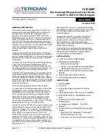
7.Assemble a spacer and a 1-5/8" flat washer onto the

end of the axle that has the small hole. See figure 3.

8.Turn the idler wheel (no hole in hub) so that the air valve

faces out. Place onto the axle and secure with a 1-5/8"
dia. flat washer and a 1/8" x 1-1/2" cotter pin. Use the
extra washer if needed to take up play. See figure 3.

5.Align the holes in the ends of the two hitch braces with

the nearest hole in the hitch tube. Fasten with a 1/4" x
1-3/4" hex bolt and a 1/4" hex lock nut. See figure 2. 

DO

NOT TIGHTEN AT THIS TIME.

3/8" HEX

LOCK NUT

3/8" FLAT

WASHER

1/4" x 1-3/4"

HEX BOLT

1/4" HEX

LOCK NUT

3/8" HEX

BOLT

CROSSOVER

TUBE

HITCH BRACES

HITCH

TUBE

HOPPER

FRAME

SHAFT SUPPORT

PLATE

SMALL HOLE

SPACER

1-5/8" DIA.
FLAT WASHER

1-5/8" DIA.
FLAT WASHER

1/8" x 1-1/2"
COTTER PIN

AIR VALVE

FIGURE 3

Summary of Contents for 45-01872

Page 1: ...CAST SPREADER Model No 45 01872 FORM NO 48315 4 02 xxxxxxxxxxxxxxxxxxxxxxxxxxxxxxxxxxxxx xxxxxxxxxxxxxxxxxxxxxxxxxxxxxxxxxxxxxxxxxx xxxxxxxxxxxxxxxxxxxxxxxxxxxxxxxxxxxxxxxxxxx xxxxxxxxxxxxxxxxxxxxxxxxxxxxxxxxxxxxxxxxx xxxxx xxxxx xxxxxx xxx xxxxx xxxxx xxxxxx xxx xxxxxxxxxxxxxxxx xxxxx xxxxxx xxxxxx xxxxx xxx xxxxxx APPLICATIONTIPS ...

Page 2: ...ootwear and do not allow anyone to ride or sit on spreader attachment frame Never allow children to operate the tractor or spreader attachment and do not allow adults to operate without proper instructions Always begin with the transmission in first low gear and with the engine at low speed and gradu ally increase speed as conditions permit Maxi mum towing speed 10 M P H When towing broadcast spre...

Page 3: ... Control Link S 1 Grip KEY QTY DESCRIPTION A 6 Hex Bolt 1 4 20 x 1 3 4 B 2 Hex Bolts 3 8 16 x 1 1 4 C 2 Hex Bolt 1 4 20 x 3 4 D 1 Carriage Bolt 1 4 20 x 3 4 E 8 Hex Lock Nuts 1 4 20 Thread F 2 Hex Lock Nuts 3 8 16 Thread G 2 Lock Washers 3 8 I D H 4 Nylon Washer I 8 Flat Washer 5 16 KEY QTY DESCRIPTION E F D C B A K L M G H I J N O P Q R S NOT SHOWN FULL SIZE SHOWN FULL SIZE ...

Page 4: ... using the 3 8 hex bolt flat washer and hex lock nut removed in figure 1 See figure 2 DO NOT TIGHTEN AT THIS TIME FIGURE 2 6 Tighten all hex nuts and bolts following the same sequence as assembled in figures 1 and 2 DO NOT COLLAPSE TUBE WHEN TIGHTENING 7 Assemble a spacer and a 1 5 8 flat washer onto the end of the axle that has the small hole See figure 3 8 Turn the idler wheel no hole in hub so ...

Page 5: ... pin through the hitch bracket and the hitch tube and secure with the hair cotter pin See figure 5 FIGURE 5 14 Assemble the flow control link end with small hole to the flow control arm using a 1 4 x 3 4 hex bolt a nylon washer and a 1 4 hex lock nut as shown in figure 6 Tighten carefully The flow control link should not be loose but should pivot with no more than slight resis tance FIGURE 6 1 4 H...

Page 6: ...0 19 Place the adjustable stop into the ON end of the slot in the top of the flow control mounting bracket Secure with the 1 4 x 3 4 carriage bolt a nylon washer a 5 16 flat washer and the nylon wing nut See figure 11 FLOW CONTROL ROD FLOW CONTROL LINK 3 32 COTTER PIN 5 16 FLAT WASHER SLOT FLOW CONTROL MOUNTING BRACKET 1 4 x 1 3 4 HEX BOLT 1 4 HEX LOCK NUT 5 16 FLAT WASHER 14 Assemble the flow con...

Page 7: ...djustable stop at 5 Pull flow control arm against stop Verify that closure plate has opened about half way e If closure plate does not open half way it may be closed too far at OFF Adjust position of flow control mounting bracket until closure plate will open about half way at 5 and still close when arm is locked in OFF Tighten 1 4 lock nuts FIGURE 12 5 16 FLAT WASHER NYLON WASHER 1 4 x 3 4 CARRIA...

Page 8: ...rate to maintain the same coverage The faster you drive the wider the broadcast width 6 Always start the tractor in motion before opening clo sure plate 7 Always shut the closure plate before turning or stop ping the tractor 8 If fertilizer is accidentally deposited too heavily in a small area soak the area thoroughly with a garden hose or sprinkler to prevent burning of the lawn 9 To insure unifo...

Page 9: ...t and on the axle at least once a year or more often as needed 7 Oil right hand idler wheel bearing at least once a year or more often as needed FIGURE 15 MAINTENANCE GREASE OIL OIL SPROCKET SHAFT AGITATOR WIRE 3 8 HEX NUT AGITATOR SLEEVE STORAGE 1 If the axle slotted gear and sprocket assembly is disassembled mark down the positions of the parts as they are removed The drive wheel and sprocket po...

Page 10: ...1 22 19 18 4 D E 35 50 15 37 37 39 23 A A 33 59 27 26 28 3 19 36 34 9 46 9 57 9 40 16 14 7 17 37 24 50 12 13 E 9 29 30 5 9 54 9 4 9 35 B 6 52 44 47 58 58 8 42 32 7 D 45 54 48 29 40 37 60 25 B 1 39 10 54 41 54 51 39 9 54 39 38 31 2 39 40 58 55 56 58 53 53 37 9 49 40 C 61 9 C 62 ...

Page 11: ... 29 44285 2 Bushing Delrin 30 23766 1 Sleeve Agitator 31 43878 1 Wire Agitator REF PART QTY DESCRIPTION NO NO 32 43070 5 Washer Flat 3 8 33 41576 2 Bolt Hex 3 8 16 x 1 3 4 Lg 34 44469 1 Rod Flow Control 35 23525 2 Brace Hitch 36 23762 1 Shaft Support Plate 37 1509 069 12 Bolt Hex 1 4 20 x 1 3 4 38 43015 1 Nut Hex 3 8 16 39 1543 069 12 Washer Nylon 40 43088 15 Washer Flat 1 4 Std 41 24858 1 Stop Ad...

Page 12: ...rmal maintenance 5 AGRI FAB does not extend any warranty for products sold or exported outside of the United States of America its possessions and territories except those sold through AGRI FAB s authorized channels of export distribution WHAT AGRI FAB WILL DO Repair or replace your AGRI FAB product or part HOW TO GET SERVICE Deliver the AGRI FAB product or part to AGRI FAB s local authorized serv...

Reviews: