9
●
TO ADJUST DEPTH OF CUT-
DISCONNECT TOOL
FROM POWER SOURCE.
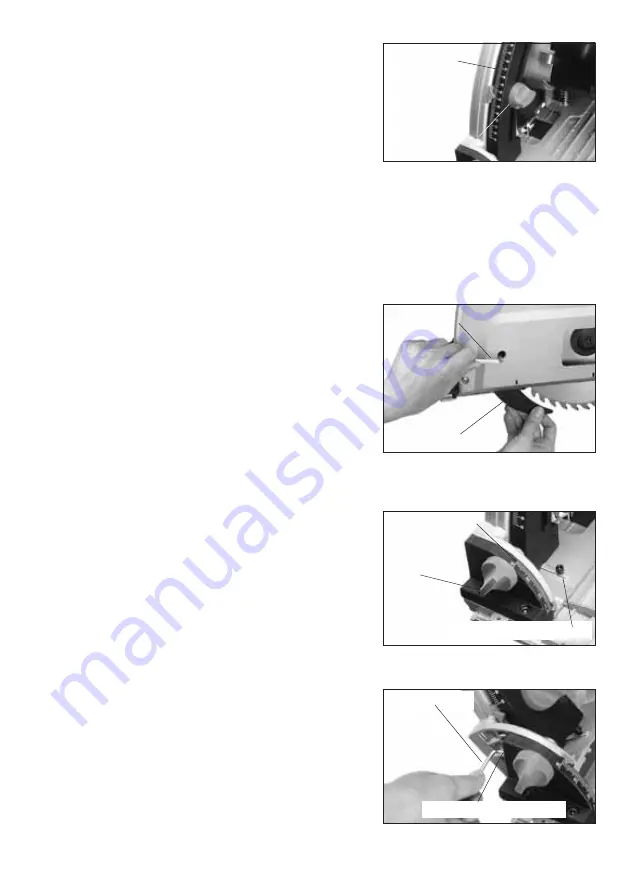
Adjust the depth of cut as desired. A depth scale is provided.
To adjust the depth of cut:
Loosen the depth lock knob about 1-1/2 turns. While pushing in
slightly, slide the depth stop up or down as desired and retighten.
See fig.5
Riving knife
This machine is fitted with a riving knife as standard. This design helps to resist kickback. For safety reasons, all
saw work should always be carried out with the riving knife installed and correctly set.
The riving knife must be set so that the distance between riving knife and cutting circle of the saw blade is
2 to 4 mm (not more than 5mm) and the rim of the blade does not extend more than 5 mm beyond the lowest edge
of the riving knife.
Setting the riving knife:
1.
Unplug the machine.
2.
Lock the saw in its blade change position for setting the riving
knife. At this position the locking bolt will line up with the port
in the cover.
3.
Loosen the locking bolt about a half turn with the hex wrench
supplied.
4.
Set the riving knife correctly, and retighten the locking bolt.
Double check the adjustment, as it is spring loaded and can
shift when being tightened. See fig.6
●
TO ADJUST BEVEL ANGLE -
DISCONNECT TOOL FROM
POWER SOURCE.
To adjust the bevel angle, refer to the bevel gauge on the base. There
are markings for different angles from 0 to 45 degrees.
To adjust the bevel angle:
Loosen both of the bevel lock knobs (See fig.7) front and rear about
a half turn, then rotate the base to the desired angle. Retighten both
bevel lock knobs to hold at the desired position.
●
TO ZERO IN THE BEVEL ANGLE -
DISCONNECT TOOL
FROM POWER SOURCE.
The bevel angles are properly set at the factory, but if the
adjustments are disturbed, there is provision for zeroing in both the
45 degree and 0 degree bevel positions. To zero the 45 degree
position, (See fig.8) using a properly sized allen hex wrench, adjust
the small set screw on the right side of the front bevel block. To
adjust the 0 degree bevel position adjust the 2 vertical socket head
screws on the base (See fig.1) located adjacent to the bevel adjustor
knobs. Check the accuracy of the angles with a suitable measuring
tool.
Fig.5
Fig.6
Depth scale
Depth lock stop
Riving knife
Hex wrench
Fig.7
Bevel scale
Bevel lock
knob
0 degree bevel positions
Fig.8
45 degree bevel positions
Hex wrench


