


46
Installation and Verification Manual
2
Installation (Getting Started)
11
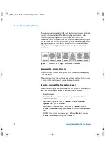
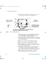
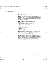
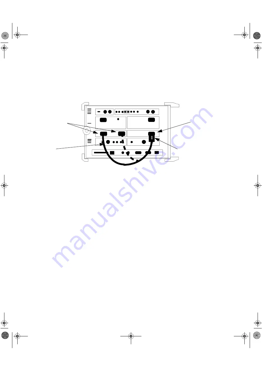
Change/Make the following Optical loopback connection to
check the 2.5 Gb/s interface as shown in
.
mm
12
Change the Transmitter Settings
Signal Rate
to
OC-48
and
set the
Wavelength
to the be same as the Transmit Port
connected in set-up, i.e.
1310nm
or
1550nm
.
13
Set the
Laser
to
ON
and check the laser LED is illuminated at
the connected 52Mb/s-2.66Gb/s Output Port on the OmniBER
OTN’s connector panel.
14
Repeat
to
to confirm correct operation.
15
Change the Transmitter Setting
Signal Rate
to
OTU-1
16
Repeat
to
to confirm correct operation.
17
Press
<Window>
key to highlight the
Transmitter Settings
page and set the
Laser
to
OFF
.
18
If the instrument has a single Receiver port covering the
range 52 Mb/s to 2.66 Gb/s skip this step and resume at
. If the instrument has two separate Receiver ports; 52
Mb/s - 622 Mb/s and 2.5 - 2.66 Gb/s continue with
19
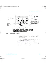
Change the Optical loopback connection to check the
622 Mb/s and below interface as shown in
Figure 4
2.5 Gb/s Loopback Connection
iii
15 dB Optical Attenuator
to ensure level is within
Receiver Input Range
Optical
Patch
Cord
Note - Either of the [52Mb/s - 2.5Gb/s] Transmitter Outputs may
be used if both 1310 and 1550 nm ports are fitted.
52 Mb/s - 2.66 Gb/s
Optical Out Ports
52-2.66 Gb/s
Optical In Port
panther3_iv.book Page 46 Wednesday, January 15, 2003 12:03 PM