


Operation
Serial BERT 12.5 Gb/s User Guide
53
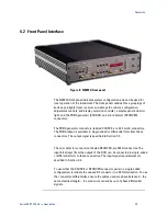
4.4
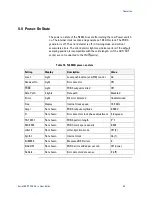
Power-On State
The power-on state of the N4962A is set after turning the rear Power switch
on. The internal clock is active and generates a 10.0 GHz clock. The PRBS
generator is off. The error detector is off, in training mode, and will not
accumulate errors. The error detector light may indicate errors if the default
sampling position is incompatible with the cable length, or if the OUT/OUT
¯¯¯
port(s) are not connected to the IN/IN
¯¯port(s).
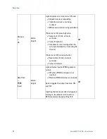
Table 16. N4962A power-on state
Setting
Display
Description
Value
Local
Light
Local push-button (vs GPIB) control
On
Receiver
On
Light
Error detector
Off
PRBS
¯¯¯¯
Light
PRBS output inverted
Off
Data Path
3 lights
Data path
Disabled
Error ε
Light
Bit error detected
Undetermined
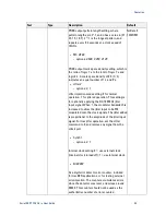
Freq
Display
Internal clock speed
10.0 GHz
Ampl
Not shown
PRBS output amplitude
0.500 V
Ø
Not shown
Error detector clock phase adjustment 0 (degrees)
PAT 2E31
Not shown
PRBS pattern length
2
31
-1
MS 0.500
Not shown
PRBS mark space density
0.500
Jitter 0
Not shown
Jitter-injection mode
Off (0)
Synth 1
Not shown
Internal clock
On (1)
Err00000
Not shown
Measured BER errors
0
ErAd OFF
Not shown
PRBS errors added per second
Off (none)
NoData
Not shown
Error detector data sense
0 (off)
Summary of Contents for N4962A
Page 1: ...Agilent N4962A Serial BERT 12 5 Gb s User Guide...
Page 6: ......
Page 16: ...Getting Started 16 Serial BERT 12 5 Gb s User Guide...
Page 24: ...N4962A System Overview 24 Serial BERT 12 5 Gb s User Guide...
Page 36: ...System Details and Performance Specifications 36 Serial BERT 12 5 Gb s User Guide...
Page 60: ...Operation 60 Serial BERT 12 5 Gb s User Guide...
Page 86: ...Remote GPIB Interface 86 Serial BERT 12 5 Gb s User Guide...
Page 88: ...Copyright Agilent Technologies 2012 Third edition May 2013 Printed in Germany...


