


System Details and Performance Specifications
Serial BERT 12.5 Gb/s User Guide
33
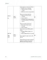
The error detector compares the sampled input bit stream to a separate
internal PRBS signal generated with the same configuration settings as the
PRBS generator. The error detector automatically synchronizes its internal
PRBS with the incoming bit stream, in a process called ‘training’. The error
detector is in training mode when off, and switches to error-counting mode
when the detector is turned on. Assuming the training was successful, and the
error detector was able to synchronize with the input bit stream, the detector
starts counting errors less than 1us after turning on.
Training the error detector takes approximately 50 us, and requires a
somewhat error-free input bit stream. If the detector is unable to synchronize
with the incoming bit stream, the measured BER will be very high. This is only
an issue for bit error rates higher than 5E-01 (50% of incoming bits are errors);
for most applications with high BER, the detector will auto-synchronize very
rapidly.
The phase adjustment offers 2 degree resolution capability from 5 Gb/s to
12.5 Gb/s. The linearity accuracy of phase is limited to 10 degree steps for
operation from 5 Gb/s to 12.5 Gb/s. For external clock rates below 5 GHz the
specific values of 0, 90, 180 or 270 degrees are required for the receiver clock
phase alignment in order to obtain correct BER results. Employing the
receiver’s auto-phase feature or manual adjustment to the receiver phase
resulting in any other phase values may lead to receive errors. Users requiring
greater precision in receiver clock and data alignment below 5 GHz can achieve
this result using external means such as a mechanical phase-shifter.
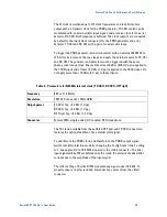
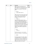
Table 8
.
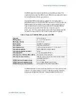
Parameters for N4962A error detector (IN, IN
¯¯)
Data rate
0.5 to 12.5 Gb/s
PRBS patterns
2
n
– 1, n=7, 10, 15, 23, 31
Data input sensitivity (single ended)
0.1 V pp typical
Data input voltage range
2 Vpp max (single-ended)
± 0.5 V DC common mode voltage max
Data input phase adjust
0 to 360°
Data input phase adjust resolution
2° for data rates ≥ 5 Gb/s
90° for data rates < 5 Gb/s
Data input external interface
Differential. DC coupled, 50 Ω nominal, female SMA
(May be operated single end without unused input
terminated into 50 Ω)
RXCKI Clock input frequency range
0.5 to 12.5 GHz
RXCKI Clock input amplitude range
+4 to +10 dBm (1 to 2 V pp)
RXCKI Clock input external interface
AC coupled, 50 Ω nominal, female SMA
Summary of Contents for N4962A
Page 1: ...Agilent N4962A Serial BERT 12 5 Gb s User Guide...
Page 6: ......
Page 16: ...Getting Started 16 Serial BERT 12 5 Gb s User Guide...
Page 24: ...N4962A System Overview 24 Serial BERT 12 5 Gb s User Guide...
Page 36: ...System Details and Performance Specifications 36 Serial BERT 12 5 Gb s User Guide...
Page 60: ...Operation 60 Serial BERT 12 5 Gb s User Guide...
Page 86: ...Remote GPIB Interface 86 Serial BERT 12 5 Gb s User Guide...
Page 88: ...Copyright Agilent Technologies 2012 Third edition May 2013 Printed in Germany...


