


Production Setup and Testing
i3070 Series 5i Help
4-3
Production Testing
1
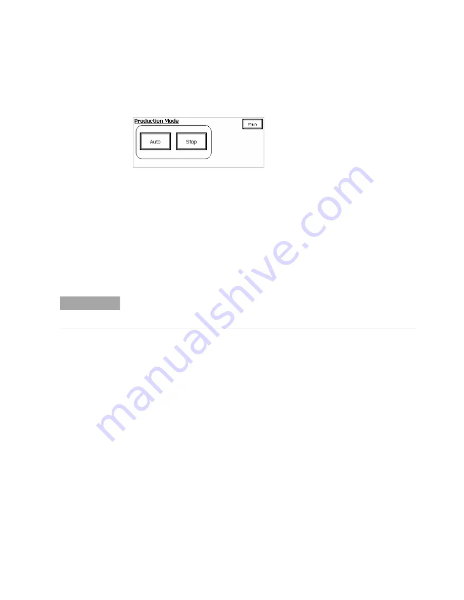
On the LCD touch panel, select
Production
mode.
2
Launch the Medalist i3070 software.
3
Load and run the testplan.
•
When the testplan starts, commumication is established between the
controller and PLC.
•
Settings are verified and the fixture ID is read.
•
The Press is initialized.
•
On the touch panel, Production mode is automatically set to
Auto
and
the system is ready to receive a board and begin testing.
Use the Engineer Test Interface for test debugging when needed.
Using the
Break
key on the keyboard will stop the testplan. In case communication with
the controller is lost, press and hold
Stop
on the LCD touch panel to stop the testplan
running.
NOTE
Summary of Contents for Medalist i3070 Series 5i
Page 1: ...Agilent Technologies Medalist i3070 Series 5i Inline ICT System i3070 Series 5i Help...
Page 6: ...vi...
Page 18: ...1 12 i3070 Series 5i Help Getting Started...
Page 26: ...2 8 i3070 Series 5i Help Touch Panel Functions...
Page 38: ...3 12 i3070 Series 5i Help Test Development Figure 3 10 ID Block Location Dimensions in mm...
Page 52: ...3 26 i3070 Series 5i Help Test Development...
Page 56: ...4 4 i3070 Series 5i Help Production Setup and Testing...
Page 88: ...6 20 i3070 Series 5i Help Troubleshooting...
Page 92: ...7 4 i3070 Series 5i Help Replacement Procedures Figure 7 2 Stowing the guide bar Guide Bar...
Page 140: ...7 52 i3070 Series 5i Help...
Page 151: ...9 1 Medalist i3070 Series 5i ICT System i3070 Series 5i Help Appendix Electrical Diagrams 9 2...
Page 153: ...i3070 Series 5i Help 9 3 Figure 9 1 Sensor Layout 1...
Page 154: ...9 4 i3070 Series 5i Help Figure 9 2 Sensor Layout 2...
Page 155: ...i3070 Series 5i Help 9 5 Figure 9 3 Sensor Layout 3...
Page 156: ...9 6 i3070 Series 5i Help Figure 9 4 Sensor Layout 4...
Page 157: ...i3070 Series 5i Help 9 7 Figure 9 5 Power Circuit 1...
Page 158: ...9 8 i3070 Series 5i Help Figure 9 6 Power Circuit 2...
Page 159: ...i3070 Series 5i Help 9 9 Figure 9 7 Power Circuit 3...
Page 160: ...9 10 i3070 Series 5i Help Figure 9 8 Power Circuit 4...
Page 161: ...i3070 Series 5i Help 9 11 Figure 9 9 Power Circuit 5...
Page 162: ...9 12 i3070 Series 5i Help Figure 9 10 Pneumatic 1...
Page 163: ...i3070 Series 5i Help 9 13 Figure 9 11 Pneumatic 2...
Page 164: ...9 14 i3070 Series 5i Help Figure 9 12 Pneumatic 3...
Page 165: ...i3070 Series 5i Help 9 15 Figure 9 13 PLC Input Unit Channel 0...
Page 166: ...9 16 i3070 Series 5i Help Figure 9 14 PLC Input Unit Channel 1...
Page 167: ...i3070 Series 5i Help 9 17 Figure 9 15 PLC Input Unit Channel 2...
Page 168: ...9 18 i3070 Series 5i Help Figure 9 16 PLC Input Unit Channel 3...
Page 169: ...i3070 Series 5i Help 9 19 Figure 9 17 PLC Input Unit Channel 4...
Page 170: ...9 20 i3070 Series 5i Help Figure 9 18 PLC Output Unit Channel 10...
Page 171: ...i3070 Series 5i Help 9 21 Figure 9 19 PLC Output Unit Channel 11...
Page 172: ...9 22 i3070 Series 5i Help Figure 9 20 PLC Output Unit Channel 12...
Page 173: ...i3070 Series 5i Help 9 23 Figure 9 21 Motor and Communication...
Page 174: ...9 24 i3070 Series 5i Help Figure 9 22 PLC to PC Interface...
Page 175: ...i3070 Series 5i Help 9 25 Figure 9 23 Interfacinng Cables...
Page 176: ...9 26 i3070 Series 5i Help Figure 9 24 SMEMA Communication...
Page 177: ...i3070 Series 5i Help 9 27 Figure 9 25 Touch Panel...
Page 178: ...9 28 i3070 Series 5i Help Figure 9 26 Servo Motor...
Page 179: ...i3070 Series 5i Help 9 29 Figure 9 27 Servo Pin Connection...
Page 180: ...9 30 i3070 Series 5i Help Figure 9 28 Analog Card Interface...
Page 181: ...i3070 Series 5i Help 9 31 Figure 9 29 Stepper Motor...


