


6-4
i3070 Series 5i Help
Troubleshooting
Error Messages and Remedial Actions
If error messages appear on the LCD touch panel, press
OK
and take
action as described in
Table 6-2
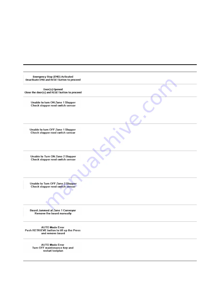
Error Messages
Error Message
Cause/Action
1
Release the Emergency Stop switch by turning it clockwise.
2
Press the Reset button.
1
Close the door(s) and press Reset.
1
Check that the air supply is turned on.
2
Check the Zone 1 stopper cylinder and replace if faulty.
3
Check the Up reed switch for the Zone 1 stopper (RS-1) and adjust if
needed.
4
Replace the Up reed switch if faulty.
1
Check that the air supply is turned on.
2
Check the Zone 1 stopper cylinder and replace if faulty.
3
Check the Down reed switch for the Zone 1 stopper (RS-2) and
adjust if needed.
4
Replace the Down reed switch if faulty.
1
Check that the air supply is turned on.
2
Check the Zone 2 stopper cylinder and replace if faulty.
3
Check the Up reed switch for the Zone 2 stopper (RS-19) and adjust
if needed.
4
Replace the Up reed switch if faulty.
1
Check that the air supply is turned on.
2
Check the Zone 2 stopper cylinder and replace if faulty.
3
Check the Down reed switch for the Zone 2 stopper (RS-20) and
adjust if needed.
4
Replace the Down reed switch if faulty.
If a board could not be moved, the error message will show the location
of the jam.
•
Remove the board from the indicated location.
A board is present when the system tries to start Auto mode operation.
1
Manually move the Press to its origin position.
2
Remove the board from the system.
The Maintenance Key Switch is ON when the system tries to start Auto
mode operation.
1
Turn the Maintenance Key Switch to the OFF position.
2
Restart the testplan.
Summary of Contents for Medalist i3070 Series 5i
Page 1: ...Agilent Technologies Medalist i3070 Series 5i Inline ICT System i3070 Series 5i Help...
Page 6: ...vi...
Page 18: ...1 12 i3070 Series 5i Help Getting Started...
Page 26: ...2 8 i3070 Series 5i Help Touch Panel Functions...
Page 38: ...3 12 i3070 Series 5i Help Test Development Figure 3 10 ID Block Location Dimensions in mm...
Page 52: ...3 26 i3070 Series 5i Help Test Development...
Page 56: ...4 4 i3070 Series 5i Help Production Setup and Testing...
Page 88: ...6 20 i3070 Series 5i Help Troubleshooting...
Page 92: ...7 4 i3070 Series 5i Help Replacement Procedures Figure 7 2 Stowing the guide bar Guide Bar...
Page 140: ...7 52 i3070 Series 5i Help...
Page 151: ...9 1 Medalist i3070 Series 5i ICT System i3070 Series 5i Help Appendix Electrical Diagrams 9 2...
Page 153: ...i3070 Series 5i Help 9 3 Figure 9 1 Sensor Layout 1...
Page 154: ...9 4 i3070 Series 5i Help Figure 9 2 Sensor Layout 2...
Page 155: ...i3070 Series 5i Help 9 5 Figure 9 3 Sensor Layout 3...
Page 156: ...9 6 i3070 Series 5i Help Figure 9 4 Sensor Layout 4...
Page 157: ...i3070 Series 5i Help 9 7 Figure 9 5 Power Circuit 1...
Page 158: ...9 8 i3070 Series 5i Help Figure 9 6 Power Circuit 2...
Page 159: ...i3070 Series 5i Help 9 9 Figure 9 7 Power Circuit 3...
Page 160: ...9 10 i3070 Series 5i Help Figure 9 8 Power Circuit 4...
Page 161: ...i3070 Series 5i Help 9 11 Figure 9 9 Power Circuit 5...
Page 162: ...9 12 i3070 Series 5i Help Figure 9 10 Pneumatic 1...
Page 163: ...i3070 Series 5i Help 9 13 Figure 9 11 Pneumatic 2...
Page 164: ...9 14 i3070 Series 5i Help Figure 9 12 Pneumatic 3...
Page 165: ...i3070 Series 5i Help 9 15 Figure 9 13 PLC Input Unit Channel 0...
Page 166: ...9 16 i3070 Series 5i Help Figure 9 14 PLC Input Unit Channel 1...
Page 167: ...i3070 Series 5i Help 9 17 Figure 9 15 PLC Input Unit Channel 2...
Page 168: ...9 18 i3070 Series 5i Help Figure 9 16 PLC Input Unit Channel 3...
Page 169: ...i3070 Series 5i Help 9 19 Figure 9 17 PLC Input Unit Channel 4...
Page 170: ...9 20 i3070 Series 5i Help Figure 9 18 PLC Output Unit Channel 10...
Page 171: ...i3070 Series 5i Help 9 21 Figure 9 19 PLC Output Unit Channel 11...
Page 172: ...9 22 i3070 Series 5i Help Figure 9 20 PLC Output Unit Channel 12...
Page 173: ...i3070 Series 5i Help 9 23 Figure 9 21 Motor and Communication...
Page 174: ...9 24 i3070 Series 5i Help Figure 9 22 PLC to PC Interface...
Page 175: ...i3070 Series 5i Help 9 25 Figure 9 23 Interfacinng Cables...
Page 176: ...9 26 i3070 Series 5i Help Figure 9 24 SMEMA Communication...
Page 177: ...i3070 Series 5i Help 9 27 Figure 9 25 Touch Panel...
Page 178: ...9 28 i3070 Series 5i Help Figure 9 26 Servo Motor...
Page 179: ...i3070 Series 5i Help 9 29 Figure 9 27 Servo Pin Connection...
Page 180: ...9 30 i3070 Series 5i Help Figure 9 28 Analog Card Interface...
Page 181: ...i3070 Series 5i Help 9 31 Figure 9 29 Stepper Motor...


