


3-22
i3070 Series 5i Help
Test Development
Learn Press Heights
The press positions described in
need to be set according to the
fixture/pin design. Follow the procedure below to set these press positions.
The taught positions are automatically saved to the 75 mm, 85 mm or
100 mm fixture profile. They need not be set again when reloading the
same fixture or another fixture with the same key characteristics.
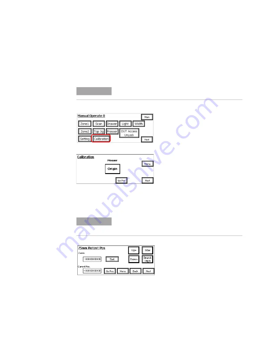
1
In Maintenance Mode, select
Calibration
.
2
Press
Origin
to move the Press to the start position.
3
Press
Next
to continue.
Press
Next
to skip the
Standby Pos
and
Presser Retrieve Pos
pages.
(That is, keep the factory settings for those positions.)
4
Begin calibration with the
Retest Pos
.
a
Press
Search Origin
to move the Press to the start position.
b
Press
Up+
or
Down–
to move the Press to the desired position.
Use
Slow
to slow down the Press movement if needed.
c
Press
Set
to save the taught position.
5
Press
Next
to learn the next position. See
.
A password is required to access the Calibration pages.
Also turn the Maintenance Key Switch to ON.
There are separate calibration pages for the 75 mm, 85 mm and
100 mm fixture. Check the title of the page and make sure it is
correct for your fixture.
Z-axis
shows the saved position.
Current Pos
shows the current position
as the Press is moved.
NOTE
NOTE
Summary of Contents for Medalist i3070 Series 5i
Page 1: ...Agilent Technologies Medalist i3070 Series 5i Inline ICT System i3070 Series 5i Help...
Page 6: ...vi...
Page 18: ...1 12 i3070 Series 5i Help Getting Started...
Page 26: ...2 8 i3070 Series 5i Help Touch Panel Functions...
Page 38: ...3 12 i3070 Series 5i Help Test Development Figure 3 10 ID Block Location Dimensions in mm...
Page 52: ...3 26 i3070 Series 5i Help Test Development...
Page 56: ...4 4 i3070 Series 5i Help Production Setup and Testing...
Page 88: ...6 20 i3070 Series 5i Help Troubleshooting...
Page 92: ...7 4 i3070 Series 5i Help Replacement Procedures Figure 7 2 Stowing the guide bar Guide Bar...
Page 140: ...7 52 i3070 Series 5i Help...
Page 151: ...9 1 Medalist i3070 Series 5i ICT System i3070 Series 5i Help Appendix Electrical Diagrams 9 2...
Page 153: ...i3070 Series 5i Help 9 3 Figure 9 1 Sensor Layout 1...
Page 154: ...9 4 i3070 Series 5i Help Figure 9 2 Sensor Layout 2...
Page 155: ...i3070 Series 5i Help 9 5 Figure 9 3 Sensor Layout 3...
Page 156: ...9 6 i3070 Series 5i Help Figure 9 4 Sensor Layout 4...
Page 157: ...i3070 Series 5i Help 9 7 Figure 9 5 Power Circuit 1...
Page 158: ...9 8 i3070 Series 5i Help Figure 9 6 Power Circuit 2...
Page 159: ...i3070 Series 5i Help 9 9 Figure 9 7 Power Circuit 3...
Page 160: ...9 10 i3070 Series 5i Help Figure 9 8 Power Circuit 4...
Page 161: ...i3070 Series 5i Help 9 11 Figure 9 9 Power Circuit 5...
Page 162: ...9 12 i3070 Series 5i Help Figure 9 10 Pneumatic 1...
Page 163: ...i3070 Series 5i Help 9 13 Figure 9 11 Pneumatic 2...
Page 164: ...9 14 i3070 Series 5i Help Figure 9 12 Pneumatic 3...
Page 165: ...i3070 Series 5i Help 9 15 Figure 9 13 PLC Input Unit Channel 0...
Page 166: ...9 16 i3070 Series 5i Help Figure 9 14 PLC Input Unit Channel 1...
Page 167: ...i3070 Series 5i Help 9 17 Figure 9 15 PLC Input Unit Channel 2...
Page 168: ...9 18 i3070 Series 5i Help Figure 9 16 PLC Input Unit Channel 3...
Page 169: ...i3070 Series 5i Help 9 19 Figure 9 17 PLC Input Unit Channel 4...
Page 170: ...9 20 i3070 Series 5i Help Figure 9 18 PLC Output Unit Channel 10...
Page 171: ...i3070 Series 5i Help 9 21 Figure 9 19 PLC Output Unit Channel 11...
Page 172: ...9 22 i3070 Series 5i Help Figure 9 20 PLC Output Unit Channel 12...
Page 173: ...i3070 Series 5i Help 9 23 Figure 9 21 Motor and Communication...
Page 174: ...9 24 i3070 Series 5i Help Figure 9 22 PLC to PC Interface...
Page 175: ...i3070 Series 5i Help 9 25 Figure 9 23 Interfacinng Cables...
Page 176: ...9 26 i3070 Series 5i Help Figure 9 24 SMEMA Communication...
Page 177: ...i3070 Series 5i Help 9 27 Figure 9 25 Touch Panel...
Page 178: ...9 28 i3070 Series 5i Help Figure 9 26 Servo Motor...
Page 179: ...i3070 Series 5i Help 9 29 Figure 9 27 Servo Pin Connection...
Page 180: ...9 30 i3070 Series 5i Help Figure 9 28 Analog Card Interface...
Page 181: ...i3070 Series 5i Help 9 31 Figure 9 29 Stepper Motor...


