


Installation Note E8362-90004
17
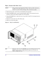
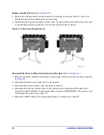
Replace the Test Set Deck Front Panel and the A25 and A26 Test Port Couplers
Remove the Existing Test Set Deck Front Panel
(Refer to
1. Disconnect the wrapped wire cable (item
①
) from the front-panel LED board.
2. Disconnect the remaining RF cable (item
②
) from each test port coupler.
3. Using a T-10 TORX driver, remove eight screws (items
❶
through
❽
) from the test set
deck front panel, to release it.
4. Remove the test set deck front panel from the analyzer, with the LED board and both
couplers attached.
5. Using a 1-inch wrench, remove the flange nut (item
③
) from each coupler. Retain the
flange nuts for installation of the new couplers. Discard the front panel and the couplers.
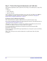
Figure 9
Test Set Deck Front Panel Replacement


