


Installation Note E8356-90052
7
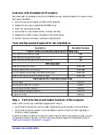
Overview of the Installation Procedure
Note that step 2 is necessary only for the E8356A network analyzer because it requires a new
A12 source assembly.
1. Verify the serial and option numbers of the analyzer.
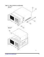
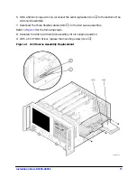
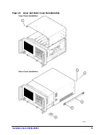
2. Replace the A12 source assembly (E8356A only).
3. Enter the new model number.
4. Verify that the new model number is shown correctly.
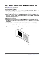
5. Replace the model number nameplate on the front panel.
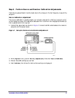
6. Perform source and receiver calibration adjustments.
Tools and Equipment Required for the Installation
Step 1.
Verify the Serial and Option Numbers of the Analyzer
Refer to the License Key Certificate supplied with the kit:
• Verify that the analyzer’s serial number matches the serial number on the certificate.
• Verify that the option number on the certificate is either 1F6 (for a 6 GHz upgrade) or
1F9 (for a 9 GHz upgrade).
If either the serial number or the option number does not match the expected results, you will
not be able to install the option. If this is the case, contact Agilent for assistance. Refer to
“Getting Assistance from Agilent” on page 5
Description
Model/Part Number
Tools for A12 Source Assembly Replacement (E8356A Only)
T-10 TORX driver (set to 9 in-lbs)
N/A
T-20 TORX driver (set to 21 in-lbs)
N/A
5/16-inch open-end torque wrench (set to 10 in-lb)
N/A
ESD Equipment
ESD grounding wrist strap
9300-1367
5 ft grounding cord for wrist strap
9300-0980
2 x 4 ft conductive table mat and 15 ft grounding wire
9300-0797
ESD heel strap (for use with conductive floors)
9300-1308
Test Equipment for Calibration Adjustments
Power meter
E4419B
Power sensor (100 kHz–4.2 GHz)
8482A
Power sensor (10 MHz–18 GHz)
E4412A
Type-N adapter (female-to-female)
1250-0777
Type-N RF cable
N6314A