


12 Verification
POWER-ON Checkout
1.
Connect the instrument to the power source and turn the front power switch to ON (1).
2.
Listen to confirm the modules' fans are on.
The power supply undergoes a selftest when you turn it on. The power-on selftest sequence tests the microprocessor, GPIB
interface, and serial communications.
Selftest Sequence
3.
All display digits and annunciators on the keyboard briefly turn on.
4.
All front panel LEDs and annunciators on the modules briefly turn on.
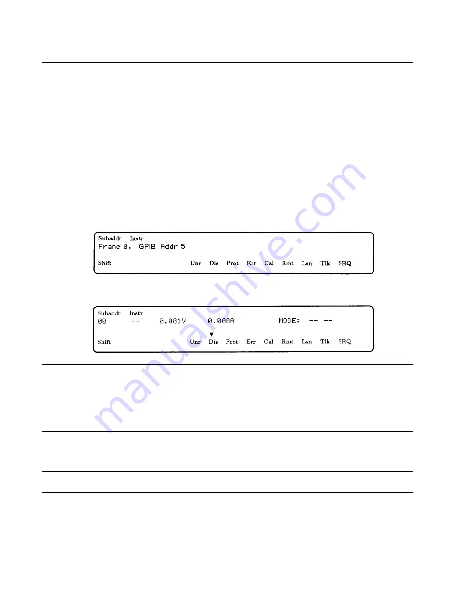
5.
The keyboard briefly displays the message:
6.
The keyboard then displays the state of the addressed module.
Note
The information displayed on the keyboard assumes:
•
At least one power module is installed,
•
Factory default state still stored in location 0,
•
Frame mode switch on the back of the mainframe is set to
MAIN
,
•
GPIB address of the mainframe is set to 5,
•
Module configuration switches set to factory default states (all OPEN).
In Case of Trouble
Note
In case of a module failure, the front panel will display an Error Code -Uxx. Refer to the Agilent
Series
661xxA Service Manual
for information on troubleshooting the dc power modules.
A problem exists in the mainframe when one of these conditions is observed during selftest:
Summary of Contents for 66000A
Page 20: ......
Page 23: ...Troubleshooting 23 Figure 4 1 Overall Troubleshooting Sheet 1 of 7...
Page 24: ...24 Troubleshooting Figure 4 1 Overall Troubleshooting Sheet 2 of 7...
Page 25: ...Troubleshooting 25 Figure 4 1 Overall Troubleshooting Sheet 3 of 7...
Page 26: ...26 Troubleshooting Figure 4 1 Overall Troubleshooting Sheet 4 of 7...
Page 27: ...Troubleshooting 27 Figure 4 1 Overall Troubleshooting Sheet 5 of 7...
Page 28: ...28 Troubleshooting Figure 4 1 Overall Troubleshooting Sheet 6 of 7...
Page 29: ...Troubleshooting 29 Figure 4 1 Overall Troubleshooting Sheet 7 of 7...
Page 30: ...30 Troubleshooting Figure 4 2 Bias Troubleshooting Sheet 1 of 2...
Page 31: ...Troubleshooting 31 Figure 4 2 Bias Troubleshooting Sheet 2 of 2...
Page 32: ...32 Troubleshooting Figure 4 3 ROM Microprocessor Troubleshooting...
Page 43: ...TP 0 TP 1 TP 2 TP 4 TP 5 TP 8 TP 7 TP 9 TP10 TP11 TP12 TP13 COM TP14 TP 3 TP 6...
Page 44: ......
Page 45: ......
Page 46: ......
Page 47: ......
Page 48: ......
Page 50: ......