background image

Setting Up the Oscilloscope

To verify basic oscilloscope operation

1-30

To verify basic oscilloscope operation

1

Connect an oscilloscope probe to channel 1.

2

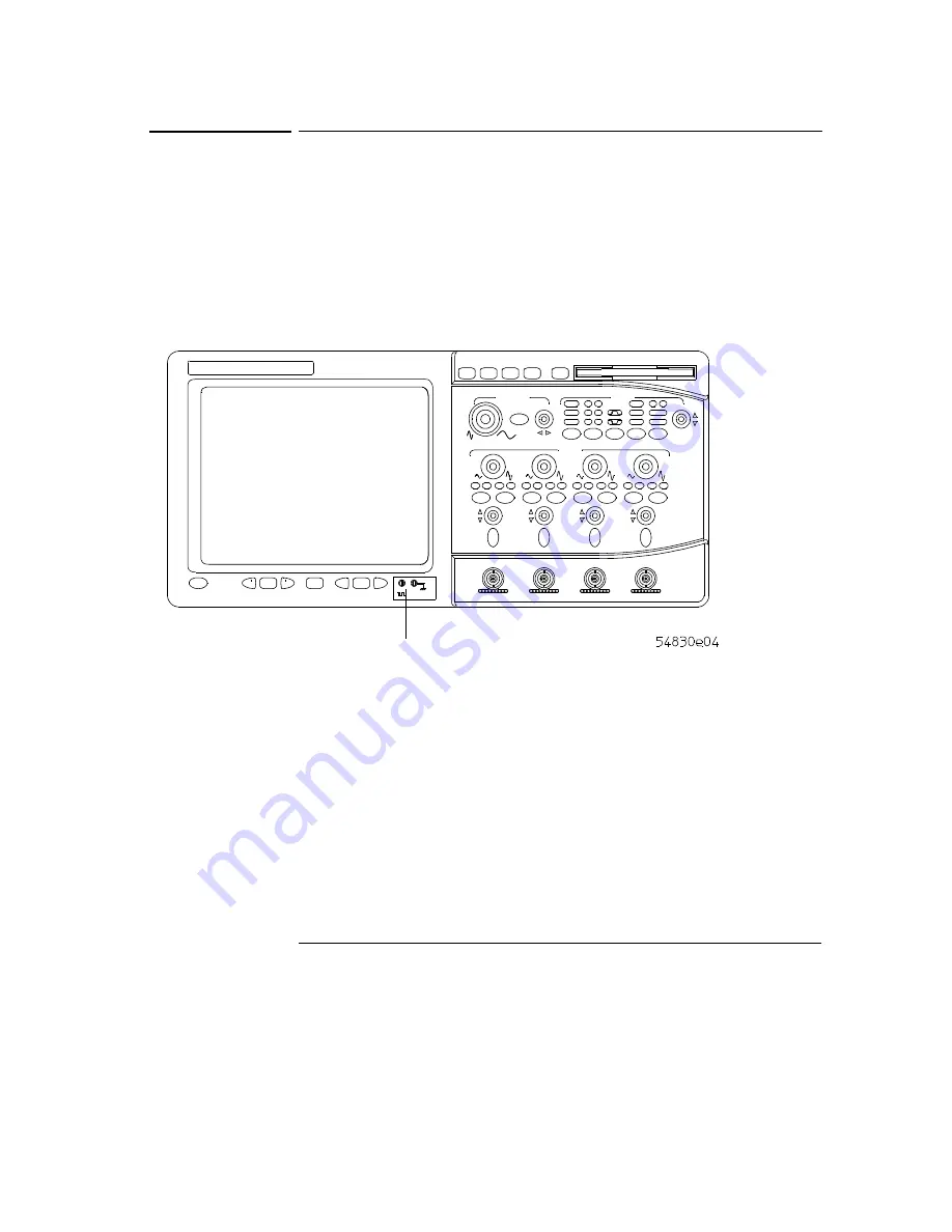
Attach the probe to the calibration output on the front panel of the 
oscilloscope.

Use a probe grabber tip so you do not need to hold the probe.   The calibratation 
output is marked with a square wave symbol.

Figure 1-23

Verifying Basic Oscilloscope Operation

3

Press the Default Setup key on the front panel.

The display will pause momentarily while the oscilloscope is configured to its 
default settings.

4

Press the Autoscale key on the front panel.

The display will pause momentarily while the oscilloscope adjusts the sweep 
speed and vertical scale.  You should then see a square wave with peak-to-peak 
amplitude of approximately 5 divisions and a period of almost 3 divisions.  If you 
do not see the waveform, ensure your power source is adequate, the 
oscilloscope is properly powered-on, and the probe is connected securely to the 
front-panel channel input BNC and to the probe calibration output.

Calibration

Output

Summary of Contents for 54830A

Page 1: ...Agilent Keysight 54830D Manual Get Pricing Availability at ApexWaves com Call Today 1 800 915 6216 Email sales apexwaves com https www apexwaves com oscilloscopes keysight technologies 54830 series 54830D ...

Page 2: ...number 54830 97005 August 2002 For Safety information and Regulatory information see the pages at the end of this manual Copyright Agilent Technologies 2001 2002 All Rights Reserved 54830A 31A 32A and 54830D 31D 32D Infiniium Oscilloscopes ...

Page 3: ... Built In Information System Chapter 4 describes the built in information system contents and navigation The built in information system contains all of the information that is generally found in a User s Guide C A U T I O N The Infiniium Oscilloscope uses a specially designed Windows 98 application program While it is possible to access some standard Windows 98 application programs it is not reco...

Page 4: ...5 To connect an GPIB cable 1 26 To tilt the oscilloscope upward for easier viewing 1 27 To turn on the oscilloscope 1 28 To turn off the oscilloscope 1 29 To verify basic oscilloscope operation 1 30 To clean the oscilloscope 1 32 2 Working in Comfort About Repetitive Strain Injury 2 3 Mice and Other Input Devices 2 4 3 Using the Oscilloscope Front Panel 3 4 Acquisition and General Controls 3 5 Hor...

Page 5: ...d full screen mode 3 30 To perform basic user interface operations 3 31 To select a command from the menu bar 3 33 To select a command from a context sensitive menu 3 34 To change the mouse settings 3 36 To start and stop waveform acquisition 3 37 To clear the waveform display 3 38 To print the screen 3 39 To turn a channel on or off 3 40 To adjust the vertical offset 3 41 To adjust vertical scali...

Page 6: ...the Built In Information System To access the information system 4 4 Access Methods 4 5 To navigate through the information system 4 10 For most topics 4 10 For Setup Guide topics 4 10 To access context sensitive information 4 11 ...

Page 7: ...Contents 4 ...

Page 8: ...1 Setting Up the Oscilloscope ...

Page 9: ...1 2 Setting Up the Oscilloscope This chapter shows you how to set up your Infiniium oscilloscope connect power and accessories and verify general operation ...

Page 10: ...h Programmer s Guide Service Guide and Probe manuals in Adobe Acrobat format See figure 1 1 See table 1 2 for the power cord If anything is missing contact your nearest Agilent Technologies Sales Office If the shipment was damaged contact the carrier then contact the nearest Agilent Technologies Sales Office Inspect the oscilloscope If there is mechanical damage or a defect or if the oscilloscope ...

Page 11: ... 1 4 Figure 1 1 Package Contents for the Infiniium Oscilloscopes Infiniium Oscilloscope with Accessory Pouch 1165A Probe 54830 and 54831 models only User s Quick Start Guide Mouse Keyboard Digital Probe 5483xD models only Digital Clip Leads 5483xDmodelsonly ...

Page 12: ...4 61604 1 2 Probe Power Fan Out for use with 1144A and 1145A 10076A 4 kV 250 MHz High Voltage Probe 10467 68701 4 IC Clips 0 5 mm N2771A 10 kV 50 MHz High Voltage Probe 10450A SMT Probe Accessory Kit 10833A GPIB cable 1 m 10833B GPIB cable 2 m 10833C GPIB cable 4 m 10833D GPIB cable 0 5 m 1142A Probe control and power module 1184A Testmobile with keyboard and mouse tray accessories draw 1250 2427 ...

Page 13: ...mm spacing 8 signals E2621A 75 Ω terminator E2622A 100 110 120 Ω differential terminator E2625A Communication Mask Test Kit Option E2635A VoiceControl Upgrade Kit E2643A Wedge Adapter 0 5 mm spacing 16 signals E2644A Wedge Adapter 0 65 mm spacing 16 signals E2645A USB Test Option for 54831 and 54832 only E2646A SQiDD Fixture for USB option E2654A EZ Probe Positioner E2813A Wedge Adapter 0 5 mm spa...

Page 14: ...tion the oscilloscope where it will have sufficient clearance for airflow around the top back and sides Figure 1 2 Positioning the Infiniium Oscilloscope with Sufficient Clearance Minimum 0 mm Minimum 85 mm both sides Minimum 39 mm Airflow requirements 250 cfm Minimum 22 mm ...

Page 15: ...illoscope Power Cord Connection The oscilloscope power supply automatically adjusts for line input voltages in the range 100 to 240 VAC Therefore you do not need to adjust an input line voltage setting The line cord provided is matched by Agilent Technologies to the country of origin from which it is ordered 3 Ensure that you have the correct line cord See table 1 2 ...

Page 16: ...Cyprus Nigeria Zimbabwe Singapore Opt 901 8120 0696 Australia New Zealand Opt 902 8120 1692 East and West Europe Saudi Arabia So Africa India unpolarized in many nations Opt 903 8120 1521 United States Canada Mexico Philippines Taiwan Opt 906 8120 2296 Switzerland Opt 912 8120 2957 Denmark Opt 917 8120 4600 Republic of South Africa India ...

Page 17: ...18 8120 4754 Japan Opt 919 8120 6799 Israel Opt 920 8120 6871 Argentina Opt 921 8120 6979 Chile Opt 922 8120 8377 China Opt 927 8120 8871 Thailand These cords are included in the CSA certification approval of the equipment Plug Type Agilent Part No Country ...

Page 18: ...lloscope Figure 1 4 Connecting the Mouse Cable While you can operate many oscilloscope functions using only the front panel keys and knobs you will need the mouse to access advanced oscilloscope functions through the graphical interface or to find out more about the oscilloscope through the built in information system 2 To modify the mouse configuration see To change the mouse settings in Chapter ...

Page 19: ...anel of the oscilloscope Figure 1 5 Connecting the Keyboard The keyboard simplifies some oscilloscope tasks such as entering file names when you store waveforms and setups to the disk 2 If you need more desk space place the keyboard on top of the oscilloscope Do not stack other objects on the keyboard this will cause self test failures on power on ...

Page 20: ...t to the LAN card 1 Connect your LAN cable to the RJ 45 connector on the LAN card Make sure the connection is secure Figure 1 6 Connecting to the LAN Card 2 AfteryouhaveconnectedtotheLANcard youmustsetupthenetwork Go to To set up the network in chapter 3 RJ 45 Connection ...

Page 21: ...onnect oscilloscope probes 1 14 To connect oscilloscope probes 1 Attach the probe connector to the desired oscilloscope channel or trigger input Push it straight on until it latches into place Figure 1 7 Attaching the Probe Connector ...

Page 22: ...Setting Up the Oscilloscope To connect oscilloscope probes 1 15 2 Connect the probe to the circuit of interest using grabbers or other probing aids Figure 1 8 Probing the Circuit ...

Page 23: ...e oscilloscope without twisting it Figure 1 9 Disconnecting the Oscilloscope Probe C A U T I O N Do not attempt to twist the snap on probes on or off the oscilloscope s BNC connector Twisting the probe connector body will damage it C A U T I O N Do not exceed the maximum input voltage rating The maximum input voltage for 50 Ω inputs is 5 Vrms CAT I Maximum voltage at 1 MΩ impedance is 100 V dc ac ...

Page 24: ... the tab key facing left into the digital connector 2 Tighten both thumb screws Figure 1 10 Connecting the Digital Cable to the Oscilloscope The 5483xD Infiniium oscilloscopes are the only oscilloscopes that have 16 digital channels The digital clip lead marked clk clock is unused All the other digital click leads are used for the digital channels ...

Page 25: ...used to connect to the circuit C A U T I O N Do not exceed the maximum input voltage rating of 40 V peak CAT I Probe tip isolation network and equivalent load The probe tips of the probe lead set contain an isolation network which serves to minimize the loading effect of the digital channels on the circuit under test The isolation network schematic is shown in Figure 1 12 The 5483xD Infiniium osci...

Page 26: ...n Network The loading effect of the probe tip on the circuit under test is represented by the circuit is shown in the equivalent load schematic in Figure 1 13 Figure 1 13 Equivalent Load including oscilloscope 250 Ω Signal 90 9 kΩ 8 2 pF To Oscilloscope 370 Ω 7 4 pF 1 5 pF 100 kΩ Signal ...

Page 27: ... rating of 40 V peak CAT I The isolation network must be used on all digital channels for this to be valid Note 5 V is supplied by the oscilloscope to provide power for the demo board DO NOT connect these pins to the circuit board under test D0 37 D1 35 D2 33 D3 31 D4 29 D5 27 D6 25 D7 23 D8 21 D9 19 D10 17 D11 15 D12 13 D13 11 D14 9 D15 7 Do not connect 5 Unused 3 5 V see note 1 5 V see note 39 3...

Page 28: ...illoscope Digital probe lead set 1 21 For more information on digital probing solutions search for the document titled Probing Solutions for Logic Analysis Systems on the Agilent Technologies web site at www agilent com ...

Page 29: ...4398A cable plus the 34399A adapter kit Some printers may require other cable configurations but the oscilloscope has a 9 pin serial connector Go to step 5 1 Attach the 25 pin small D connector to the printer output connector on the rear of the oscilloscope Tighten the thumbscrews to secure the cable Figure 1 15 Attaching the Small D Connector 2 Attach the larger 36 pin D connector to the printer ...

Page 30: ...or Parallel interface if necessary See the documentation for your printer 4 Go to To install the printer software in Chapter 3 5 Connect the 9 pin D connector of the serial printer cable to the serial output port on the rear panel of the oscilloscope Tighten the thumbscrews to secure the cable Figure 1 17 Attaching the 9 pin D Connector Port on Printer ...

Page 31: ...he serial input port of the printer Tighten the thumbscrews to secure the cable Figure 1 18 Attaching the 25 pin D Connector 7 Set the printer configuration to use the serial interface See the documentation for your printer 8 Go to To install the printer software in Chapter 3 Port on Printer ...

Page 32: ...monitor You can connect a VGA compatible monitor to the Infiniium oscilloscope to provide a larger viewing area 1 Connect the monitor cable to the display board video connector at the rear panel of the oscilloscope 2 Tighten the retaining screws Figure 1 19 Connecting an External Monitor ...

Page 33: ...connect an GPIB cable 1 26 To connect an GPIB cable 1 Attach the GPIB connector to the GPIB interface card connector at the rear of the oscilloscope 2 Tighten the thumbscrews on the connector Figure 1 20 Attaching the GPIB Connector ...

Page 34: ...rd for easier viewing 1 27 To tilt the oscilloscope upward for easier viewing 1 Lift up the front of the oscilloscope grasp the wire bail near the center and pull it down and forward until it latches into place Figure 1 21 Latching the Oscilloscope Front Feet ...

Page 35: ...es and accessories before applying power You can connectanddisconnectprobesandthekeyboardwhiletheoscilloscope is turned on Screen Saver The oscilloscope display has a screen saver that turns off the backlight when there has been no front panel or graphical interface activity for a pre determined period The default time is 8 hours and is configurable through the Display Setup dialog in the graphica...

Page 36: ...of the oscilloscope front panel Even though the Infiniium oscilloscope is based on the Windows 98 operating system shuting down the oscilloscope without going through the normal Windows 98 shutdown process is perfectly safe The Infiniium oscilloscope software was designed making sure not to do anything which requires going through a normal shutdown ...

Page 37: ... Setup key on the front panel The display will pause momentarily while the oscilloscope is configured to its default settings 4 Press the Autoscale key on the front panel The display will pause momentarily while the oscilloscope adjusts the sweep speed and vertical scale You should then see a square wave with peak to peak amplitude of approximately 5 divisions and a period of almost 3 divisions If...

Page 38: ...ght corner of the display 6 Move the mouse around and verify that the pointer follows on the screen If the pointer does not move ensure that the mouse is properly connected that you have clicked the correct button to enable the graphical interface and that the mouse is on a medium friction surface Figure 1 24 Graphical Interface Enable Button With the mouse pointer ontheright handbutton click the ...

Page 39: ... clean the oscilloscope Clean the oscilloscope with a soft cloth dampened with a mild soap and water solution C A U T I O N Do not use too much liquid in cleaning the oscilloscope Water can enter the Infiniium front panel damaging sensitive electronic components ...

Page 40: ...2 Working in Comfort ...

Page 41: ...in the hands and arms If you experience discomfort or pain while using the oscilloscope discontinue use immediately and consult your physician as soon as possible For more information on RSI you may wish to consult the About Repetitive Strain Injury section Please study the recommendations offered here in this chapter Included there are references to relevant parts of international standards regul...

Page 42: ...form repetitive tasks such as assembly line work meatpacking sewing playing musical instruments and computer work RSI also has been observed in those who frequently engage in activities such as carpentry knitting housework gardening tennis windsurfing and lifting children What causes RSI The specific causes of RSI have not been established Nevertheless the incidence of RSI has been associated with...

Page 43: ...e the buttons or scroll wheel on your mouse scrolling mouse trackball or other input device Using too much force can place unnecessary stress on the tendons and muscles in your hands wrists and forearms If you are using a scrolling mouse be sure to keep your fingers and hand in a relaxed neutral position when activating the scroll wheel Also this type of mouse features software that can minimize t...

Page 44: ...3 Using the Oscilloscope ...

Page 45: ...Front Panel on page 3 3 The graphical interface with menus windows dialogs and toolbars provides easy logical access to dozens of configuration and analysis tools making it easy for you to set up and make the most complex measurements The interface also allows you to use the Infiniium oscilloscope s built in information system which gives detailed information on using the oscilloscope to make meas...

Page 46: ...addition thefront panel has a set of LED Light Emitting Diode indicators by using these and the display you can assess the configuration of the oscilloscope at a glance there is no need to enter a series of keystrokes to navigate through complex menus The Infiniium Oscilloscope uses color consistently throughout the front panel and user interface For example the color of the knob for channel 1 is ...

Page 47: ...ront panel you can configure the Infiniium Oscilloscope for most troubleshooting tasks The control categories are Acquisition and general controls Horizontal controls Trigger controls Vertical controls Marker and measurement controls Marker and Measurement Controls Vertical controls Acquisition and general controls Horizontal controls Power Switch Trigger controls ...

Page 48: ...e conditions on which the oscilloscope will trigger andacquirean input signal Youcan setupavariety of trigger conditions Edge and glitch triggers can be selected from the front panel and the parameters for edge triggering can be set up here as well Some glitch trigger parameters such as glitch width and all advanced trigger configurations are set up using the graphical interface Trigger configurat...

Page 49: ... By default the markers track the source waveform Voltage measurements from the markers are the value of the waveform at the time set with the marker arrow keys The QuickMeas key initiates four preset measurements on the waveforms Both quick measurements and markers will function on any input waveform simply continue to press and release one of the keys either QuickMeas Marker A or Marker B to cyc...

Page 50: ...t Setup key If you use the Default Setup key with the graphical interface enabled you can select Undo Default Setup from the Control menu to return the oscilloscope to its original configuration Save the Current Oscilloscope Configuration Before using Default Setup you may want to save the current oscilloscope configuration for lateruse Seethebuilt in informationsystem described in chapter 4 for i...

Page 51: ...ignal it finishes acquiring data updates the display then starts another acquisition cycle if it is in triggered or auto trigger mode If it is in single sweep mode it stops after updating the display To stop waveform acquisition press the Stop key The oscilloscope stops acquiring data Whatever data was last acquired remains on the screen Figure 3 2 Run and Stop Keys Start waveform acquisition Stop...

Page 52: ...he waveform display If the oscilloscope is in Run mode and is receiving triggers it will update the display as it collects new waveform data Clearing the waveform display also resets averaging infinite persistence and color grade persistence histogram and mask testing database Figure 3 3 Clear Display Key Erases the current waveform display ...

Page 53: ...also increases the display update rate While a analog channel is turned off data acquisition continues for that channel Therefore you can still use the analog channel as a source for functions Figure 3 4 Channel Key Using an Analog Channel as External Trigger Any analog channel can be used as a trigger source If you need an external trigger but do not need all analog channels you can use an analog...

Page 54: ...mber key until it is illuminated To turn them off press the digital channel number key again Figure 3 5 Digital Channels Key Digital channels are only available on the 5483xD Infiniium oscilloscopes The only digital channels that are displayed are the ones that are turned on in the Digital Setup dialog box Use this key to turn digital channels on or off ...

Page 55: ... Ω and 1 MΩ To change the input coupling press the Coupling key until the LED for the desired coupling is illuminated Choices are AC and DC If you change the input coupling to AC when 50 Ω impedance is selected the input impedance changes to 1 MΩ If you change the input impedance to 50 Ω the input coupling changes to DC Figure 3 6 Input Impedance and Coupling Use this key to change the input coupl...

Page 56: ...eform bigger There are fewer volts displayed per division Increasing the vertical scale makes the waveform smaller There are more volts displayed per division To move the waveform toward the top of the display turn the vertical offset knob clockwise To move it toward the bottom of the display turn the knob counter clockwise The vertical offset knob is the smaller of the two knobs for a channel It ...

Page 57: ...turn the size knob clockwise To make it smaller turn the knob counter clockwise To move the waveform toward the top of the display turn the vertical offset knob clockwise To move it toward the bottom of the display turn the knob counter clockwise Figure 3 8 Digital Channel s Vertical Size and Offset Controls Digital channels are only available on the 5483xD Infiniium oscilloscopes Vertical offset ...

Page 58: ...clockwise To move the waveform to the left turn the horizontal position knob counter clockwise Moving the waveform to the right shows more of the pre trigger data data acquired before the trigger event Moving the waveform to the left shows more of the post trigger data data acquired after the trigger event The horizontal position knob is the smaller of the two horizontal control knobs It is marked...

Page 59: ...waveform data A section of the waveform in the main sweep window is highlighted to indicate the part shown in the delayed sweep window The horizontal sweep speed and horizontal position controls now change how the waveform is shown in the delayed sweep window The sweep speed will change the amount of magnification while the position will change the part of the waveform in the main sweep window tha...

Page 60: ...trigger on a rising or falling edge 4 Press the Sweep key until the Trig d LED is illuminated The oscilloscope will wait for the edge before initiating a sweep 5 Select an input coupling for the trigger signal by pressing the Coupling key You can choose DC AC LF Reject or HF Reject See the built in Information System for more information on when to use each type of coupling 6 Turn the Level knob t...

Page 61: ... press the Marker B key Marker B has a dashed line pattern on the waveform display It is associated with the first available source on the display Press the key again to move to the next available source When there are no more sources the marker turns off To move a marker on the waveform press and hold the left arrow or right arrow key next to the desired Marker key Release the key when the marker...

Page 62: ...ress the QuickMeas key until that waveform is the one shown in the measurement readout Continuing to press the QuickMeas key cycles through each of the waveforms available To turn off the quick measurement display press and release the QuickMeas key until the measurements are turned off The measurement results disappear from the screen See the built in information system described in Chapter 4 for...

Page 63: ...ey down powerup procedure 1 Turn off the power to the oscilloscope 2 Turn on the power to the oscilloscope 3 Hold downanyoneofthearrow keysnext to theMarkerAandMarker B keys 4 When the oscilloscope display appears release the key you held down in step 3 A key down powerup completely reinitializes the oscilloscope including the configuration RAM It does not affect saved waveforms or setups which ar...

Page 64: ...e menus and toolbars so you can concentrate on your measurement In full screen mode the display looks like the following two figures Figure 3 15 Infiniium Oscilloscope Top of Display in Full Screen Mode Memory bar highlighted area shows how much of acquisition memory is displayed on the screen Vertical status bar only channels that are on are shown in matching colors Waveform display area Current ...

Page 65: ...Display in Full Screen Mode Trigger level Sweep speed Run stopmode run shown in green stop in red Horizontal and trigger status bar Horizontal position delay Horizontal reference indicators left center right horizontal delay is time at the highlighted arrow Trigger level reference indicator ...

Page 66: ...o switch between the graphical interface and full screen mode on page 3 30 Figure 3 17 Infiniium Oscilloscope Top of Display in Graphical Interface Mode This button enables the graphical interface Menu bar Measurement toolbar can be turned off Set vertical scaling Turn this channel on or off Access the ChannelSetup dialog box Memory bar highlighted area shows how much of acquisition memory is disp...

Page 67: ...ng and offset settings ground reference indicator and measurements done on that channel also have the same color You can still use the front panel when the graphical interface is enabled All changes made tothe front panel settings are reflected inthe graphical interface and changes made using the graphical interface are reflected in the front panel where applicable Use whichever interface is easie...

Page 68: ...rement to be made on that edge You can also make a measurement by simply clicking the icon on the measurement toolbar then selecting the source to be measured in the dialog box that appears When you start a measurement this way any measurements on waveform specific features will measure the first appropriate feature on the waveform For example a rise time measurement will measure the first rising ...

Page 69: ...orange border to reflect the type of markers being displayed For example when the Histogram tab is selected the markers are histogram markers and are used to define the histogram window Waveform Display Area The waveform display area shows the waveforms and optionally the results of your measurements Several display options including a grid are available and can be configured using the graphical i...

Page 70: ...s like figure 3 17 and figure 3 18 including a menu bar measurement toolbar if enabled and graphical controls for vertical horizontal trigger and acquisition You can switch to full screen mode to maximize the waveform viewing area and eliminate the menu bar measurement toolbar and other graphical controls You can use the menu bar for most oscilloscope configuration functions Context sensitive menu...

Page 71: ...licking on this stops acquisition Same as pressing the Stop key on the front panel The rightmost is a small windshield wiper Clicking on this clears acquired waveform data from the display Same as pressing the Clear Display key on the front panel Horizontal settings and controls The middle of the bar contains the horizontal settings and controls Leftmost is a button labeled with an H Clicking on t...

Page 72: ...e waveforms expand and contract about this reference position Trigger settings and controls The right side of the bar contains the trigger settings and controls These will vary depending on the current trigger configuration which can be set using the front panel and the graphical interface Advanced trigger configuration items are available only through the graphical interface You can click on the ...

Page 73: ...rmation system To enable full screen mode click the larger square wave button in the upper right hand corner of the display The button changes state and the menus and measurement toolbar disappear Choosing this option allows you to focus only on the waveform and measurement You must make changes to the oscilloscope configuration using the front panel Figure 3 20 Interface Mode Control Buttons Use ...

Page 74: ...ifferent dialog boxes in the oscilloscope graphical interface See the Persistence radio buttons in figure 3 21 You can choose only one option at a time To use a check box click the mouse button with the pointer in the box A check mark in the box indicates that item is selected See the Connect Dots check box in figure 3 21 To clear the selection click the mouse button with the pointer in the box To...

Page 75: ...these radio buttons to select Minimum Variable or Infinite persistence Click on the upward arrow in this spin box to increase the intensity of the grid Click on the slider arrow and move it down to decreaseor moveit up to increase the intensity of the grid Click and drag the title bar to move the dialog box on the screen Click one of these Close buttons to close the dialog box toseetheoptions youc...

Page 76: ...use button after step 1 release the button in step 3 to execute the command Some menus have submenus These are indicated by an arrow at the right side of the command When you move the pointer to one of these menu commands the submenu automatically appears You can then move the pointer to the desired command on that submenu and click the mouse button to execute the command Figure 3 23 Selecting a C...

Page 77: ...erface item in which they are found They are available in the following display areas memory bar measurement toolbar waveform display area and horizontal settings and controls 2 Click the right mouse button 3 Move the pointer to the desired menu item 4 Click the mouse button If you continue to hold the mouse button after step 2 release the button in step 4 to execute the command Figure 3 24 Select...

Page 78: ...isition Setupcontext sensitive menu Right clickinthisregion toseetheMeasurement Setupcontext sensitive menu Right click in this region to see the horizontal trigger and run controls context sensitive menu Right click in the waveform display area to see the waveform context sensitive menu Right clickinthisregion to see the Sample Rate and Sample Time selection menu ...

Page 79: ...u are left handed or simply find it more comfortable to use the mouse or other pointing device on the left side of the oscilloscope swapping the functions of the mouse buttons can make the mouse easier to use Changing the double click time primarily affects double clicks in the Open and Save Waveform and Open and Save Setup dialog boxes See the built in information system described in chapter 4 fo...

Page 80: ...the waveform display area See figure 3 27 You can still use the Run and Stop keys on the front panel while the graphical interface is enabled However if you are performing many graphical interface operations it is easier to start and stop the oscilloscope using the buttons in the interface so you do not have to remove your hand from the mouse Figure 3 27 Start and Stop Icons Click this button to s...

Page 81: ...See figure 3 28 You can still use the Clear Display key on the front panel while the graphical interface is enabled Clearing the display removes all displayed waveform data in preparation for another acquisition It also resets all automatic measurements and measurement statistics Figure 3 28 Clearing the Display Click this button to clearthewaveform display ...

Page 82: ...he print button at the bottom of the waveform display See figure 3 29 Infiniium prints the screen to the default printer according to the configuration that you have selected in the Printer Setup dialog box Figure 3 29 Printing the Screen Click this button to print the screen ...

Page 83: ... waveform display and also increases the display update rate When you turn off a channel the current vertical scaling factor and vertical scale buttons for that channel disappear They re appear when you turn the channel on You can also turn a channel on or off by using the Channel Setup dialog box or by using the front panel key for that channel Figure 3 30 Turning a Channel On or Off Turn a chann...

Page 84: ...ton in the vertical toolbar then set the vertical offset using the spin box control in the Channel Setup dialog box If you leave the mouse pointer on the waveform without clicking the mouse the pointer changes into crossed arrows as a visual indicator that you can drag the waveform when you click and hold the mouse button If you move the mouse up or down the interface constrains the movement verti...

Page 85: ... Vertical Offset or click on the waveformanddragit up or down to do the same thing or click on the ground reference indicator and drag it up or down to change the vertical offset Click to access the Channel Setup dialog then set vertical offset using the spin box or numeric keypad ...

Page 86: ... the setting is color coded to match the waveform color for easy recognition You can also adjust the vertical scaling by clicking on the current setting which is shown next to the waveform buttons for the channel This displays a pop up numeric keypad that allows you to set an exact value for the scaling Or you can adjust the vertical scaling through the Channel Setup dialog box See To access the c...

Page 87: ...probe using the Probes button You can set attenuation ratio attenuation units and measurement units for the probe or perform a probe calibration For Agilent Technologies probes that are compatible with the AutoProbe Interface the oscilloscope will automatically set these characteristics except for skew after identifying the probe when it is connected to the channel input Figure 3 33 Accessing the ...

Page 88: ...enter and right horizontal reference points This is the position of the trigger if the horizontal position is set to zero delay A non zero horizontal position value is the time relative to the trigger event at the selected horizontal reference point Figure 3 34 Horizontal Reference Points Click to set the horizontal reference to the left side of the display Click to set the horizontal reference to...

Page 89: ... based on your selection You can also adjust the sweep speed by clicking on the current setting This displays a pop up numeric keypad that allows you to set an exact value for the sweep speed Or you can adjust the sweep speed through the Horizontal Setup dialog box See To access the horizontal setup on page 3 48 Figure 3 35 Adjusting Sweep Speed Clicktostretchthe waveform fewer seconds per divisio...

Page 90: ...to the position value at the bottom of the waveform display Or click and hold the mouse button on the desired waveform and drag the waveform to the right or left Release the mouse button when the waveform is in the desired position When you click and drag a waveform this changes the horizontal position for all channels and functions on the display but not that of waveform memories You can also adj...

Page 91: ...ng the Horizontal Setup menu you can set sweep speed position and the horizontal reference You can also set up the delayed time base window which uses software expansion to present a magnified view of an area of the waveform See the built in information system described in chapter 4 for details Figure 3 37 Accessing the Horizontal Setup or select this menu item to access the horizontal setup dialo...

Page 92: ...e verticaloffset sweep speed and horizontal position as necessary to best rescale the area you defined in step 1 If stopped the oscilloscope does a software magnification of the waveform In either case a small dialog box appears in the corner of the screen with a single Undo button by clicking this button you will undo the zoom and return the oscilloscope to its previous settings Avoid Overdriving...

Page 93: ... section of the waveform 3 50 Figure 3 38 Zooming on a Section of the Waveform Click and hold the mouse button drag to create a selection rectangle then click inside the rectangle to zoom the display on the waveforms inside the rectangle ...

Page 94: ...drag the marker to the position you want on the waveform Release the mouse button Clicking and dragging a marker makes it easy to quickly move the marker to the desired waveform event You can use the front panel arrow keys for fine adjustment Or you can select the Markers command from the Measure menu and set the marker position precisely See the built in information system for details Figure 3 39...

Page 95: ...available by selecting them from the Measure menu When you drag and drop a measurement icon on a waveform notice that the icon outline changes color to match the color of each waveform it touches This enables you to easily see which waveform will be measured when you release the mouse button Also the measurement results are also displayed in color to make it easy to see which waveform source is be...

Page 96: ... measurement on a waveform 3 53 Figure 3 40 Waveform Measurements In some cases geometric icons are also displayed to associate the measurement Channel numbers associate the measurement results with the channelwaveform being measured ...

Page 97: ... dialog allows you to select any of the different modes of triggering supported by the oscilloscope Edge Glitch or Advanced with choices under Advanced of Pattern State Delay by Time Delay by Events Violation or Video You can set the parameters and conditions for each of those trigger modes Figure 3 41 Accessing the Trigger Setup Click this button to access the trigger setup dialog or select this ...

Page 98: ...r the trigger signal 4 Click to select either the rising or falling edge of the trigger source 5 Set the trigger level using the spin box You can also click on the trigger level setting to display a pop up numeric keypad where you can enter the trigger level directly Figure 3 42 Setting an Edge Trigger Select Triggered sweep orSinglefor single shot acquisition Select rising or falling edge Set the...

Page 99: ...o see the results of your changes immediately without closing the dialog box To allow multiple dialog boxes on the screen at a time select Utilities then User Preferences Then select Allow Multiple Active Dialogs in the User Preferences dialog box Normally the oscilloscope displays only one dialog box at a time and you must close that dialog box before opening another With Allow Multiple Active Di...

Page 100: ...t dialog box preferences 3 57 Figure 3 43 Setting Dialog Box Options Select one of these commands to change how dialog boxes look on the screen Select this command to allow many dialog boxes to be present on the screen at one time ...

Page 101: ...Using the Oscilloscope To set dialog box preferences 3 58 Figure 3 44 Multiple Active Dialogs Opaque ...

Page 102: ...correct options for the printer you are configuring to use 1 If the scope is not in the graphical interface mode enable the mode by clicking on the mouse icon in the upper right corner This displays the menu options you need to configure the printer setup See To switch between the graphical interface and full screen mode on page 3 30 2 Select File Print Setup and Add Printer A window appears with ...

Page 103: ...ctions on the screen you will complete the printer installation process as described on the screen and on the following pages If you are adding a plug and play printer the installation process will automatically continue after powerup Follow instructions displayed on the screen If you are adding a printer that is NOT plug and play or a network printer after powerup the scope does not recognize if ...

Page 104: ...e following printer selection dialog appears Figure 3 46 Choose to Set Up Local or Network Printer 8 If you are going to use a network printer click Network printer If you are going to use a local printer connected to the scope s printer port go directly to step 12 You do not have to configure the scope s printer port if you are setting up the scope to use a network printer ...

Page 105: ...er For example lrnprod 4si_pcl In this example lrnprod is the network server name and 4si_pcl is the network printer name 11 Click Yes or No to select whether to use this printer as the default printer When the process for installing the network printer finishes you can choose to print a test page if you want The remaining steps continue the process of installing a local printer 12 Click Local pri...

Page 106: ...r installation process finishes the scope displays the printer port selection dialog Figure 3 48 Printer Port Selection Dialog 15 If you connected a parallel Centronics printer to the oscilloscope select the LPT1 port If you connected a serial printer to the oscilloscope select the COM2 port 16 Click Configure Port to configure the printer port The printer port properties dialog boxes appear letti...

Page 107: ...to match the settings for your printer If you are using a parallel printer ensure that the checkbox for Spool MS DOS print jobs is cleared and that Check port state before printing is checked These dialogs that appear show example settings Figure 3 49 Port Configuration Dialogs 18 Click OK to return to the printer port selection dialog box Then click Next ...

Page 108: ...ware 3 65 Figure 3 50 Printer Name Dialog 19 Typeanamefortheprinter oracceptthedefaultnamethatisdisplayed 20 Click Yes to use this printer as the default printer Then click Next The Printer Test Page dialog appears Figure 3 51 Printer Test Page Dialog ...

Page 109: ...lays the Test Page Complete dialog Figure 3 52 Test Page Complete 23 If the page printed successfully click Yes If you have a problem with the printer see the section When Something Goes Wrong in the built in information system See chapter 4 for more information on accessing and using the built in information system You Must Now Cycle Power You must now cycle poweron the scope to have yournew prin...

Page 110: ...1 you must configure the network properties 1 Click File Then select Network and Properties The following screen is displayed Figure 3 53 Network Properties Screen 2 Unless you are the System Administrator for your company s network Agilent Technologies recommends that you have System Administrator configure the network for you 3 When you are done click OK ...

Page 111: ...se the recovery CD ROM the Infiniium hard disk is returned to the condition it was in when it left the factory 1 Put Recovery CD ROM into the CD ROM drive located on the rear panel 2 Turn off the Infiniium 3 Turn on the Infiniium Infiniium will boot from Recovery CD ROM 4 Follow the onscreen instructions 5 Once the installation is complete remove the Recovery CD ROM from the CD ROM drive 6 Turn of...

Page 112: ...4 Using the Built In Information System ...

Page 113: ...nd Grid explains how to alter the display appearance tells how to improve the display of certain kinds of waveforms and explains the X versus Y display function Triggering explains basic triggering concepts describes the trigger modes available in the Infiniium Oscilloscope and tells how to use the trigger modes Saving Waveforms Saving Setups Networking and Printing explains how to simplify your w...

Page 114: ...A Setup Guide explains the steps you take to perform various measurement and configuration tasks using the oscilloscope Twenty four different procedures are covered making it easy for you to make a measurement without having to learn a complex setup process A Technical Support page explains how to get help from Agilent Technologies on using or servicing the oscilloscope A Glossary defines all the ...

Page 115: ... for the oscilloscope information system is displayed Figure 4 1 Help Menu To Use the Information System You must select the graphical interface before you can access the information system Select the graphical interface by clicking the mouse icon in the upper right corner of the scope screen Select Contents from the Help menu to access the information system ...

Page 116: ...lowing figure Figure 4 2 Contents Topic Page You can move to the Contents topic from any other information system topic by clicking on the Contents button within that topic Closes the information system window Printsthistopicon the local printer Click on a letter to go to the Index page starting with this Click on one of these buttons to find out more about how to use the oscilloscope Clickononeof...

Page 117: ...ll always stay on top of the interface display so you can refer to it while working with the oscilloscope You can move the window around the screen or resize it to make it easier to use Moves to the Contents topic Click on a letter to move to that category in the index Click on any topic name highlighted in blue to move to that topic Returns to the last topic visited Click and drag the slider to s...

Page 118: ...an find out whether a particular item has a hyperlink by pointing to it with the mouse if it is a hyperlink the pointer will change to a hand icon Clicking once will follow the hyperlink to display a new topic with the relevant information Topic Types There are two general categories of topics in the information system First are reference topics which explain what the oscilloscope does how it does...

Page 119: ... oscilloscope These are organized as an overview with a set of tabs that show the specific steps for each part in the process The following figure shows an example Moves to the Contents topic Moves to the Index Prints this topiconthe local printer Click on any underlined topic name to show that topic Displays the list of related topics Shows you how to findtheuserinterface control discussed in the...

Page 120: ...tup Guide Topic Some setup guide topics have multiple levels because the steps depend on the type of measurement you want to make Click a tab to move to the Overview or to the details for a specific step or click on the button next to a label for a step to move to the details for that step ...

Page 121: ...e top of the Help window For Setup Guide topics To display information for another topic or category described in a hyperlink click on that hyperlink or on the button icon next to it To jump to a particular step click on the hyperlink button next to the description of that step or click the tab corresponding to that step in the Overview window The Overview window is the one you first see when you ...

Page 122: ...ck the question mark button After you click on the desired user interface element a pop up window appears describing the function or use of the element To clear the pop up window click the mouse button Figure 4 6 Getting Help on the Trigger Setup Dialog Interface Elements First Access the Graphical Interface You must select the graphical interface before you can access the information system Click...

Page 123: ...4 12 ...

Page 124: ...l interface mode 3 23 3 24 help 4 11 horizontal setup 3 23 3 24 3 48 question mark 4 11 run 3 23 3 24 stop 3 23 3 24 trigger setup 3 23 3 24 3 54 3 55 C cables 1 5 power 1 9 printer 1 22 calibration and repair service 1 5 MIL STD 1 5 output 1 30 categories of information 4 7 4 8 cautions cleaning 1 32 disconnecting probes 1 16 center horizontal reference 3 29 3 45 Centronics printers see parallel ...

Page 125: ...etting 3 17 erasing the display 3 9 3 38 error messages 4 3 external trigger setup button 3 23 3 24 F feet using 1 27 FFT functions information system 4 2 4 3 finding information 4 2 4 5 4 10 front panel 3 4 3 6 connections 1 16 interface 3 2 3 3 using with graphical interface 3 24 full screen mode 3 21 3 22 3 30 mode button 3 21 3 22 3 30 functions information system 4 2 4 3 G general controls 3 ...

Page 126: ... card 1 13 learning functions of icons 3 25 LED indicators 3 3 left horizontal reference 3 29 3 45 level trigger 3 17 3 21 3 22 3 29 3 55 limited pointer motion 3 30 line voltage 1 9 local printer 3 59 locating controls 4 3 location of trigger 3 29 M magnifying a section of the waveform 3 16 waveforms 3 5 3 49 3 50 main sweep 3 16 making measurements 3 52 oscilloscope easier to view 1 27 quick mea...

Page 127: ...rs trigger 3 54 performance specifications 4 3 plug and play printer 3 59 plugs power 1 9 pointer limited motion 3 30 moving 3 31 pointing device 1 5 connecting 1 11 verifying operation 1 30 ports printer 3 63 3 64 position adjusting analog channel s vertical 3 13 adjusting digital channel s vertical 3 14 adjusting horizontal 3 15 3 28 3 47 horizontal 3 21 3 22 3 23 3 24 3 48 positioning markers 3...

Page 128: ...m 4 3 source trigger 3 17 3 55 Source key 3 17 specifications 4 3 spin box 3 31 3 32 standard accessories 1 3 1 4 starting and stopping acquisition 3 8 3 37 statistics reset 3 38 status indicators trigger 3 5 steps in Setup Guide 4 10 Stop key 3 8 stop 3 37 button 3 23 3 24 stopping acquisition 3 5 stretching and shrinking the waveform 3 15 3 28 3 46 submenus 3 33 3 34 support information 4 3 swee...

Page 129: ...28 3 43 adjusting analog channels 3 13 adjusting digital channels 3 14 vertical settings 3 27 vertical toolbar 3 27 voltage measurements 3 6 volts per division adjusting 3 13 3 43 volts per division setting 3 21 3 22 3 23 3 24 W waveform magnifying 3 5 3 16 stretching and shrinking 3 15 waveform display area 3 22 3 26 waveform features measurements on 3 52 moving markers to 3 51 selecting for meas...

Page 130: ...ignal lines 1kV power lines IEC 61000 4 5 1995 EN 61000 4 5 1995 0 5kV line line 1kV line ground IEC 61000 4 6 1996 EN 61000 4 6 1996 3V 0 15 80 MHz IEC 61000 4 11 1994 EN 61000 4 11 1994 1 cycle 100 Canada ICES 001 1998 Australia New Zealand AS NZS 2064 1 Safety IEC 61010 1 1990 A1 1992 A2 1995 EN 61010 1 1993 A2 1995 Canada CSA C22 2 No 1010 1 1992 Additional Information The product herewith com...

Page 131: ...10 1 1990 A1 1992 A2 1995 EN 61010 1 1994 A2 1995 Canada CSA C22 2 No 1010 1 1992 USA UL 3111 1 1994 optional Additional Information The product herewith complies with the requirements of the Low Voltage Directive 73 23 EEC and the EMC Directive 89 336 EEC including 93 68 EEC and carries the CE marking accordingly European Union 1 Performance Criteria A Pass Normal operation no effect B Pass Tempo...

Page 132: ...n terminal must be connected to the earth termi nal of the power source Whenever it is likely that the ground protection is impaired you must make the instrument inoperative and secure it against any unintended operation Service instructions are for trained service personnel To avoid dangerous electric shock do not perform any service unless qualified to do so Do not attempt internal service or ad...

Page 133: ...ut notice in future editions Further to the maximum extent permitted by applica ble law Agilent disclaims all warranties either express or implied with regard to this manual and any information contained herein including but not limited to the implied war ranties of merchantability and fitness for a particular purpose Agilent shall not be liable for errors or for inci dental or consequential damag...

Reviews: