

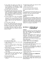

a) Two pressure test points are provided, for
measuring inlet and outlet pressures. These are
G & H on Figure 4. For convenience, a further
outlet pressure test point is provided in outlet
immediately below the control valve.
b) Pressure adjusting screw (REG.ADJ)
c) Pilot adjusting screw (PILOT ADJ). This screw is
provided on control for adjusting flow of gas to pilot
burner. The appliance is designed to operate on
full gas flow to pilot. Therefore, to ensure that full
flow is available, turn screw fully clockwise then
back 2 complete turns.
d) A screw marked NO PR. This is for rendering
inbuilt governor (i.e. pressure regulator)
inoperative, and is turned when propane is being
used. This screw must not be tampered with as its
required position will have been determined at
works.
e) A screw marked 1 STEP ADJ.
This is a device enabling the gas supply to the burner
to flow at reduced rate initially, automatically
increasing to full rate after a brief time interval.
This assists in effecting smooth ignition of the gas.
This adjustment has been correctly set at works but
should further adjustment be considered necessary,
proceed as follows:
Figure 4
2.5.5 Natural Gas Models Only
a) Adjust pressure regulator to give correct outlet
pressure of 15mbar.
b) Light oven and allow to heat up to about 150
o
C.
Then turn thermostat knob to a low setting,
shutting off burner.
c) Remove plastic cover over 1 step adjuster screw
and turn screw fully clockwise.
d) Tentatively turn screw anti-clockwise and check
ignition performance by moving thermostat knob to
a high setting.
e) Once minimum flow which ensures slow and
smooth ignition has been determined, replace
plastic cover over adjusting screw.
2.5.6 Propane Models Only
a) Remove plastic cap and turn screw NO PR fully
clockwise.
b) Adjust pressure regulator until a pressure of about
12mbar is obtained on outlet.
c) Repeat (b) to (d) as above.
d) Turn to NO PR screw fully anti-clockwise.
e) Adjust pilot adjustment screw if necessary.
Note
On no account must the NO PR screw be in an
intermediate position, i.e. it must be fully clockwise for
natural gas, or fully anti-clockwise for Propane.
2.6 INSTRUCTION TO USER
Important
After installing and commissioning appliance, hand
User Instructions to user or purchaser and ensure the
instructions for lighting, turning off, correct use and
cleaning are properly understood. The location of gas
isolating cock and electrical supply switch should be
made known to user and the procedure for that
operation in an emergency demonstrated.
SECTION 3 - SERVICING and
CONVERSION
Important
BEFORE ATTEMPTING ANY SERVICING ENSURE
THAT THE ISOLATING COCK IS TURNED OFF
AND THAT IT CANNOT BE INADVERTENTLY
TURNED BACK ON.
AFTER ANY MAINTENANCE TASK, CHECK THE
APPLIANCE TO ENSURE THAT IT PERFORMS
CORRECTLY AND CARRY OUT ANY NECESSARY
ADJUSTMENTS AS DETAILED IN SECTION 1
After carrying out any servicing or exchange of gas
carrying components -
ALWAYS CHECK FOR GAS SOUNDNESS!
3.1 GAS CONVERSION CHECK LIST
For conversion to NATURAL GAS, add the correct
governor and set the burner pressure.
For conversion to PROPANE GAS, replace the
NATURAL burner with a PROPANE burner. Remove
the governor from the gas circuit.
Other considerations -
CHANGE INJECTORS
CHANGE BYPASS SCREW AND SET LOW RATE
CHANGE DATA PLATE
3.2 REMOVAL OF PANELS and COMPONENTS
3.2.1 Oven Control Panel
Access to various electrical controls, terminals etc,
also piezo igniter, is gained upon withdrawal of the
panel. Remove the fixings which secure the panel
and draw it forward.