


c) Lift oven upon stand carefully aligning front edge of
oven base with edge of stand. From below, secure
oven to stand, using M6 x 35mm hex screws and
plain washers (2 off at front) and M5 x 16mm
hexagon screws and plain washers (2 off at rear).
d) Manoeuvre the oven and stand into its required
location, and level the assembly by turning the
adjustable feet in the stand.
e) Connect to gas and electricity supplies as detailed
in sections 1.4 and 1.5.
Note
In addition to the above, the feet can be screwed to
the floor if considered desirable, using the holes
provided in the feet.
2.1.4. G1112/2 Two Tier Oven
(See Figure 2)
These units are marked as TOP and BOTTOM ovens
before leaving the factory. Notwithstanding this, the
top unit is identified by having a worktop on top.
Proceed as follows:
a) Place the lower oven in approximately it final
location.
b) Remove the bottom grille on the upper oven. To
effect removal, slacken the two screws in the grille,
beneath the oven doors. Remove the bottom left
hand screws in the black control panel, and the two
screws in the bottom of the grille.
c) Lift the top unit onto the bottom one taking care not
to damage the upturned flange at the rear of the
bottom unit. Align back edge of base of top
unit carefully against this back flange.
d) Fix the top unit to the bottom one, using the
M6 x 50mm hexagon screws provided.
(Two at the front corners of the base, and
two at the back, through the rectangular
openings in the lower corners of the outer
back panel.
e) Fit the pipework supplied for interconnect-
ing the two individual gas inlets.
f) Manoeuvre the double unit into its final
position, and carefully level by adjusting the
levelling bolts in the base of the bottom
oven. Do not adjust more than is necessary
to effect a true level.
g) Connect to gas and electrical supplies as
detailed in sections 1.4 and 1.5.
2.1.5 Assemblyof Splashplate
and Plate Shelf
These may be supplied as optional extras,
and to assemble proceed as follows:
a) Drop the standards into the square holes at
each end of the flue outlet. On even-only
appliances secure standards at rear with
screws provided.
b) Offer the splash plate up to the standards,
with the locating brackets locating over the
flue outlet (see Figure 3).
c) Ensure the two small brackets are fitted to
the plate shelf.. Place the plate shelf over
the projecting arms of the standards and
push it back to trap the splash plate against
the vertical standards.
d) Fix the plateshelf, using the two M5
Pozidriv screws provided. If necessary,
adjust the two locating brackets to ensure
the splashplate is firmly held against the
standards.
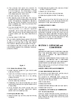
Figure 1
Figure 2
Figure 3