background image

13

PRODUCT DESCRIPTION

Button

Description

Auto Button  
(

AUTO

)

Auto Adjustment (available in VGA input only)

Press to perform auto adjustment. This function automatically tunes the LCD 
display to its optimal setting, including horizontal position, vertical position, clock, 
and phase.
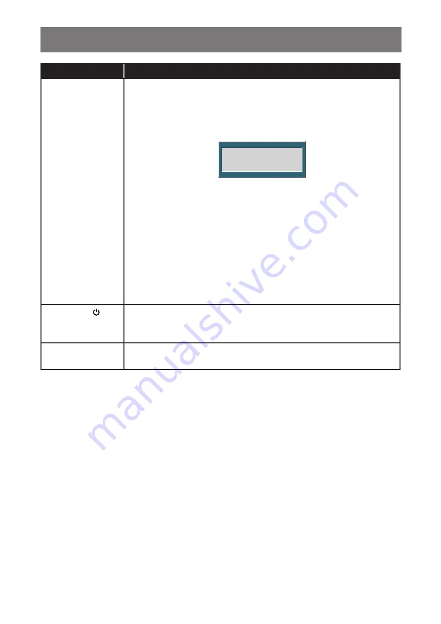
When auto adjustment is initiated, the below message is displayed on the screen. 

Auto Adjust

When the message disappears, this indicates the auto adjustment is completed.

Note:


•  During auto adjustment, the screen will slightly shake for a few seconds.
•  It is recommended to use the auto adjustment function when using the 

LCD display for the first time or after a resolution or frequency change.

During OSD menu

•  Use to close the OSD menu or exit a submenu.

During volume adjustment

•  Use to close the volume bar.

Power Button ( )

Power ON/OFF

•  Press once to turn the display ON.
•  Press again to turn the display OFF.

LED Indicator

LED lights green during normal operation and blinks green when on standby 
mode.

Summary of Contents for LA-22

Page 1: ...LA 22 LA 24 LA 27 LED Backlit Display User Manual displays agneovo com ...

Page 2: ... Control Buttons 12 1 3 3 Rear View 14 CHAPTER 2 MAKING CONNECTIONS 2 1 Connecting the AC Power 15 2 2 Connecting Input Source Signals 16 2 3 Connecting Audio Devices 17 CHAPTER 3 ON SCREEN DISPLAY MENU 3 1 Using the OSD Menu 18 3 2 OSD Menu Tree 19 CHAPTER 4 ADJUSTING THE LCD DISPLAY 4 1 Colour Setting 21 4 2 Picture Setting 22 4 3 OSD Setting 23 4 4 Other Setting 24 4 5 Reset Setting 25 CHAPTER ...

Page 3: ...ease kindly be aware that this is your responsibility to dispose electronic equipment at recycling centers so as to help conserve natural resources Each country in the European Union should have its collection centers for electrical and electronic equipment recycling For information about your recycling drop off area please contact your local related electrical and electronic equipment waste manag...

Page 4: ...o register online go to http displays agneovo com To protect your rights as a consumer do not remove any stickers from the LCD display Doing so may affect the determination of the warranty period Cautions When Setting Up Do not place the LCD display near heat sources such as a heater exhaust vent or in direct sunlight Do not cover or block the ventilation holes in the housing Place the LCD display...

Page 5: ...rd doing so may cause fire or electric shock Do not unplug or touch the power cord with wet hands WARNING Unplug the power cord from the power outlet and refer to qualified service personnel under the following conditions When the power cord is damaged If the LCD display has been dropped or the housing has been damaged If the LCD display emits smoke or a distinct odor Ceiling mount or mount on any...

Page 6: ... burn in To prevent image retention do any of the following Set the LCD display to turn off after a few minutes of being idle Use a screen saver that has moving graphics or a blank white image Switch desktop backgrounds regularly Adjust the LCD display to low brightness settings Turn off the LCD display when the system is not in use Things to do when the LCD display shows image retention Turn off ...

Page 7: ...CD Display Quick Start Guide AUTO MENU Stand for LA 24 LA 27 Base AUTO MENU Power Cord AUTO MENU Warranty Card Audio Cable LA 22 LA 24 LA 27 LA 22 LA 24 LA 27 displays agneovo com LA 22 LA 24 LA 27_Quick Guide_V010 Quick Start Guide LA 22 LA 24 LA 27 LED Backlit Display LA 22 LA 24 LA 27 Note Use only the supplied power cord The above pictures are for reference only Actual items may vary upon ship...

Page 8: ...Place the LCD display with the screen side down on a cushioned surface 2 Attach the stand to the LCD display a Press firmly on the base to secure the latches on the base into the slots on the stand b Attach the stand to the base mount LA 24 LA 27 model LA 22 LA 24 LA 27 ...

Page 9: ... Mounting To wall mount the LCD display do the following steps 1 Remove the base stand Please refer to page 28 2 Remove the base mount a Place the LCD display with the screen side down on a cushioned surface b1 Remove the screws securing the base mount to the LCD display LA 22 model b2 Push the release button and detach the stand from the base mount LA 24 LA 27 model c Pull and detach the base mou...

Page 10: ...event the LCD display from falling down and lessen possible injury and damage to the display in case of earthquakes or other disasters Use only the 100 x 100 mm wall mount kit recommended by AG Neovo All AG Neovo wall mount kits comply with VESA standard Secure the LCD display on a solid wall strong enough to bear its weight It is suggested to wall mount the LCD display without tilting it facing d...

Page 11: ...1 3 Overview 1 3 1 Front View AUTO MENU AUTO MENU AUTO MENU 1 2 1 2 1 2 LA 22 LA 24 LA 27 1 Display screen 2 Control buttons Press the button to perform its function For more information about each button refer to pages 12 13 ...

Page 12: ...ight Button t u Volume Bar Press the u button to call out the volume bar Audio Volume 50 Then press the t u button to adjust the volume level Note During volume or menu setting adjustment press and hold the t u button to change the values continuously Input Select Bar Press the t button to call out the Input Select bar VGA DP HDMI Then press the t u button to switch the input source and press the ...

Page 13: ...e disappears this indicates the auto adjustment is completed Note During auto adjustment the screen will slightly shake for a few seconds It is recommended to use the auto adjustment function when using the LCD display for the first time or after a resolution or frequency change During OSD menu Use to close the OSD menu or exit a submenu During volume adjustment Use to close the volume bar Power B...

Page 14: ...nal 3 HDMI connector Use to connect an HDMI cable for digital input signal 4 VGA connector Use to connect a VGA cable for analogue input signal 5 Audio In port 3 5mm Audio Jack Use to connect an audio cable for audio input 6 Head Phone 3 5mm Audio Jack Use to connect a head phone 7 Kensington lock socket Use to physically lock the system to prevent theft The locking device is sold separately To pu...

Page 15: ... the power is ON may cause possible electric shock or personal injury 2 1 Connecting the AC Power 1 Connect the power cord to the AC power input at the rear of the LCD display 2 Connect the plug to a power outlet or power supply AC IN CAUTION When unplugging the power cord hold the power cord by the plug head Never pull by the cord Chapter 2 Making Connections ...

Page 16: ...Port cable to the DisplayPort connector of the LCD display and the other end to the DisplayPort connector of the computer HDMI Connect one end of an HDMI cable to the HDMI connector of the LCD display and the other end to the HDMI connector of the computer VGA Connect one end of a D sub 15 pin cable to the VGA connector of the LCD display and the other end to the D sub connector of the computer ...

Page 17: ...udio Devices Audio Input Connect one end of an audio cable to the audio port of the LCD display and the other end to the audio port of the computer AUDIO IN Audio Out Audio Output Connect a headphone to the headphone jack of the LCD display ...

Page 18: ...d menu is highlighted in grey and the text of the selected menu option turns yellow 3 Press the t or u button to select an option and press the MENU button to enter its submenu 1920x1080 60Hz H Position V Position Clock Phase 50 50 50 78 1920x1080 60Hz H Position V Position Clock Phase 50 50 50 78 The text of the selected menu option or submenu turns yellow 4 Press the t or u button to adjust the ...

Page 19: ...fer to page 21 Brightness Color Temp 9300 6500 5500 USER Auto Adjust Color Adjust Picture H Position Refer to page 22 V Position Clock Phase OSD Language English Refer to page 23 Français Deutsch Italiano Русский Spanish Portuguese 日本語 한국어 繁體中文 简体中文 OSD H Pos OSD V Pos OSD Timer Transparency ...

Page 20: ...e Audio Volume Signal Source VGA HDMI DP Aspect Ratio 16 9 AUTO 4 3 Active Contrast On Off Over Drive On Off Anti Blue Light ANTI BURN IN Reset Reset Refer to page 25 Note Availability of some menu items depend on the input source signal If the menu is not available it is disabled and greyed out ...

Page 21: ...0 6500 5500 USER Colour temperature can be set to 9300 Applies a bluish tint for cooler colours 6500 This is the default colour temperature commonly used for normal lighting conditions 5500 Applies a reddish tint for warmer colours USER This allows users to set the colour temperature by adjusting the red green or blue setting according to one s preference a Select USER and press the MENU button b ...

Page 22: ...20x1080 60Hz H Position V Position Clock Phase 50 50 50 78 3 Press the t or u button to select an option and press the MENU button to enter its submenu Item Function Operation Range H Position Horizontal Position Moves the screen image to the left or right Press the t or u button to adjust the value 0 to 100 V Position Vertical Position Moves the screen image up or down Clock Adjusts the frequency...

Page 23: ... submenu Item Function Operation Range Language Choose the language used for OSD menus Press the t or u button to select the setting English Français Deutsch Italiano Русский Spanish Portuguese 日本語 한국어 繁體中文 简体中文 OSD H Pos Horizontal Position Moves the OSD window to the left or right of the screen Press the t or u button to adjust the value 0 to 100 OSD V Pos Vertical Position Moves the OSD window ...

Page 24: ...lume level of the built in speaker Press the t or u button to adjust the value 0 to 100 Signal Source Switches the input source Press the t or u button to select the setting VGA HDMI DP Aspect Ratio Selects the aspect ratio of the screen image 16 9 AUTO 4 3 Active Contrast Automatically adjusts the image contrast according to the scene Note If this function is On Colour Brightness Contrast are gre...

Page 25: ...g 1 Press the MENU button to call out the OSD window 2 Press the t or u button to select and press the MENU button to enter the Reset menu 1920x1080 60Hz Reset 1920x1080 60Hz Reset 3 Press the MENU button to restore your device to factory settings ...

Page 26: ... the refresh rate of the graphics card of the computer is set too high Change the resolution or the refresh rate of the graphics card No Input Signal The LCD display cannot detect the input source signal Check if the input source is turned ON Check if the signal cable is properly connected Check if any pin inside the cable connector is twisted or broken Chapter 5 Appendix ...

Page 27: ...djust the Clock and Phase settings in Picture menu refer to page 22 Red blue green white dots appear on the screen There are millions of micro transistors inside the LCD display It is normal for a few transistors to be damaged and to produce spots This is acceptable and is not considered a failure No audio output Check if the volume is set to 0 refer to page 12 In Other menu check if the Audio Vol...

Page 28: ...een side down on a cushioned surface b Squeeze the notches with 2 fingers on the bottom of base c Detach the base from the base mount d Push the release button and detach the stand from the base mount LA 24 LA 27 model LA 22 LA 24 LA 27 2 Put the LCD display inside its original plastic 3 Place the two foam cushions on each side of the LCD display for protection 4 Put the LCD display face down in t...

Page 29: ...cushion 6 Put all other contents on their designated area if necessary 7 Close and tape the box LA 22 LA 24 LA 27 Note It is recommended to use the original packaging box When repacking carefully place the LCD display in its box and protect the glass panel from touching any object ...

Page 30: ...Supply Internal Internal Internal Power Requirements AC 100 240V 50 60 Hz AC 100 240V 50 60 Hz AC 100 240V 50 60 Hz On Mode 18W On 18W On 25W On Stand by Mode 0 5W 0 5W 0 5W Off Mode 0 5W 0 5W 0 5W Operating Conditions Temperature 5 C 35 C 41 F 95 F 5 C 35 C 41 F 95 F 5 C 35 C 41 F 95 F Humidity 20 85 non condensing 20 85 non condensing 20 85 non condensing Storage Conditions Temperature 20 C 60 C...

Page 31: ... 0 5 0 15 0 313 0 Outline dimension 64 2 100 0 205 5 205 5 100 0 99 5 113 5 76 0 135 7 101 3 183 0 M4x10L 46 0 19 6 313 0 LA 24 46 0 20 7 433 0 555 0 Outline dimension 339 0 Outline dimension 17 4 23 6 298 0 Opening dimension 13 3 13 3 528 4 Opening dimension 226 0 227 5 227 5 146 0 100 0 93 0 118 4 140 3 5 0 20 0 94 0 339 0 80 3 100 0 226 0 M4x10L ...

Page 32: ...wan Copyright 2019 AG Neovo All rights reserved LA2700 LA2400 LA2200_UM_V010 LA 27 612 0 Outline dimension 2 0 608 0 Opening dimension 2 0 365 0 Outline dimension 2 0 342 0 Opening dimension 21 0 452 0 87 0 365 0 46 0 12 6 100 0 256 0 256 0 100 0 125 6 139 4 270 0 95 0 5 20 226 0 226 0 M4x10L ...

Reviews: