background image

Brine Tank

A large plastic tank (round OR

square/rectangular) similar to a

trash can. Inside the tank is the

brine well—a small cylinder about 4

inches (10.1 cm) in diameter—which

contains the saftey float. The brine

tank holds the salt (

not included

)

used for regeneration. There will

also be an overflow fitting and

tubing. Some systems may have a

salt grid—a plastic grid on the

bottom of the tank—but most do

not as they are not needed when

using salt pellets as recommended.

This tank holds the salt, 

DO NOT

LOAD THE RESIN IN BRINE TANK.

Bypass Valve

Depending on your order your

system will have either a single

piece stainless steel bypass or a two

part plastic bypass with yoke

connection. This is what connects to

your control head and provides

standard fitting connections to hook

up to your plumbing.

Meter Assembly

The flow meter connects the control

head and the bypass valve and it

measures the water flow to initiate

regeneration on demand. Includes

O-rings (already attached) to seal

the connection and screws and clips

to secure the connection. Typically

connected to the control head when

received.

4 of 28

Summary of Contents for Fleck 5600

Page 1: ...rther help BEFORE YOU BEGIN BASIC PLUMBING SKILLS ARE REQUIRED FOR INSTALLATION IF YOU ARE UNSURE OF YOUR ABILITIES TO INSTALL THE SYSTEM USING THESE INSTRUCTIONS PLEASE HIRE A QUALIFIED PLUMBER READ THROUGH YOUR PARTS LIST AND VERIFY ALL COMPONENTS ARE ACCOUNTED FOR AND IN GOOD CONDITION BEFORE SCHEDULING A PLUMBER PLEASE READ THROUGH THE ENTIRE INSTRUCTION MANUAL CAREFULLY IF HIRING A PLUMBER EN...

Page 2: ...power GFCI outlet is recommended Use of an extension cord is NOT recommended A 1 5 inch standpipe sump pit or outside drain Please note The drain line is pressurized and can be ran vertically if necessary 1 VERIFY SYSTEM INVENTORY Use the following table to help verify the parts that are included with your system and verify that they are all accounted for Inspect all parts for damage and report an...

Page 3: ...eing placed in service Riser Distributor Tube A tall pipe that runs from the bottom of the tank to the control valve IF YOUR TANK IS LOADED EMPTY TANKS ONLY WEIGH 20 30 POUNDS DO NOT PULL THE RISER TUBE OUT OF THE TANK One end has a basket basket design varies and it usually ships inside the tank Control Head Screws on top of the tank and controls the water flow and regeneration cycles Digital SXT...

Page 4: ...ts as recommended This tank holds the salt DO NOT LOAD THE RESIN IN BRINE TANK Bypass Valve Depending on your order your system will have either a single piece stainless steel bypass or a two part plastic bypass with yoke connection This is what connects to your control head and provides standard fitting connections to hook up to your plumbing Meter Assembly The flow meter connects the control hea...

Page 5: ...her with the tubing with the instructions or with the control head Fittings include the brass brine nut ferrule insert and screen Drain Fitting Fitting s that connect the control head to the drain line Please Note Drain line is not included Depending on the system ordered there are multiple options and the pictures shown are common examples but actual fitting may vary 5 of 28 ...

Page 6: ...ottom of polyglass tank Resin Bag s of material placed in the polyglass tank that does the actual treatment of the water Color of resin may vary Please Note Depending on system size you may receive more than one package of resin packaged differently This is normal The system is designed to use all the resin shipped with it however sometimes a resin bag can be overfilled To avoid problems DO NOT FI...

Page 7: ...x 54 12 x 48 13 x 54 14 x 65 14 x 65 Resin 0 5 ft 0 75 ft 1 25 ft 1 ft 1 5 ft 2 ft 2 5 ft 3 ft 3 5 ft Before you start plumbing 2 PRE INSTALLATION PREPARATION Money saving tip If hiring a plumber to do the installation you can save some money by preparing the tank ahead of time This cuts down on the time the plumber has to spend and doing so is simple enough that most people can accomplish it in l...

Page 8: ...gravel GRAVEL GOES IN FIRST THE RESIN GOES IN THE POLYGLASS TANK DO NOT LOAD THE RESIN IN BRINE TANK Make sure to cover the opening of the riser tube Simply put something over the end of the tube such as a piece of tape to prevent anything from falling into the riser tube IF YOU HAVE GRAVEL WITH YOUR SYSTEM IT WILL GO IN FIRST Make sure to empty all boxes to verify it is not in the bottom of the t...

Page 9: ...ry secure inside the head and almost impossible for it to come out It is also a good idea to verify that the riser tube fits snugly into the pilot hole and that the O ring seals around it 3 2 Inspect and install top distributor basket if applicable Depending on system configuration your system may include a top distributor basket Img 5 If your system includes one it is recommended that you use it ...

Page 10: ... you are having a hard time fitting your hand between the float and the brine well to secure the overflow nut you can remove the float by removing the nut that holds the float in place Make sure to put it back when you are finished Please Note Some systems may use a compression style float fitting that will look different than the style shown but will function the same way 4 2 Use 3 8 inch line to...

Page 11: ...t of the box and the initial regeneration ran after installing the system will place the initial volume of water in the brine tank 5 SETUP CONTROL HEAD 5 1 Plug control head in Plug the control head into a qualifing outlet as stated in the requirements section Please Note The control head can be plugged in and operated without water this will not damage the control head Once plugged in verify the ...

Page 12: ...setting Once the parameter display is gone press and hold the up AND down arrow buttons together for 5 10 seconds until the programming icon appears and DF is shown in the parameter code Once each setting has been entered use the extra cycle button to advance to the next setting Please Note Most of these settings will be left alone Depending on your system some settings may not be shown and some s...

Page 13: ... time in 24 hour format VT Valve Type dF1b Downflow single backwash used on softeners that require the brine draw Fltr Filter used for basic backwashing systems that do not need the brine draw dF2b Downflow double backwash similar to the dF1b but with 2 backwashes Not commonly used UFbd Upflow brine first not commonly used UFtr Uplow filter not commonly used Othr Other not commonly used CT Control...

Page 14: ... with 2 media tanks dual tank softeners only UT Indicates current tank in service U1 Tank 1 is in service U2 Tank 2 is in service dual tank softeners only C Capacity 1 999 9 x1000 System capacity in grains Metered softeners only This will be set to match your system size so a 48k or 48 000 grain system will be set to 48 Reference the tank size chart above for help in matching up your tank size wit...

Page 15: ...e number of gallons the system reserves as a saftey factor to ensure the system will treat the water until the next regeneration It is commonly set to the average number of gallons used in a day If you are unsure of your actual usage a good rule of thumb is to set it to the number of people in the house times 75 Example if there are 4 people in the house you would set it to 300 gallons 4x75 DO Day...

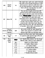
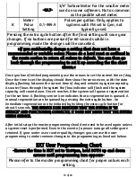
Page 16: ...nants with a strong flow of water going out the drain line Reducing this cycle can lead to reduced resin life and premature system failure For very dirty water longer times may be needed BD Brine Draw 60 This sets the length of the brine draw portion of the cycle During this cycle the water from the brine tank is rinsed slowly through the resin tank to regenerate the resin A slow flow of water wil...

Page 17: ...ion this is normal Exact amount will vary and water level in the brine tank may be above OR below the salt level depending on system brine tank and amount of salt in the tank D1 D7 Doy of the Week Setting OFF Set to On or OFF for each dayof the week Only applies to systems with Control Type dAY not typically used CD Current Day 1 7 Used to set the current day Only applies to systems with Control T...

Page 18: ...maining system capacity As water flows through the system the flow indicator will flash and the system capacity will count down Once it reaches 0 the system will queue a regeneration for the set time A flashing service icon indicates that a regeneration is queued A manual regeneration can be queued by pressing the extra cycle button An immediate regeneration can be initiated by holding the extra c...

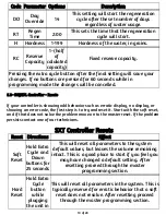
Page 19: ... display or showing an error code the first step is to try and reset it Start with the soft reset and if that does not solve the problem move on to the master reset If the problem persists contact one of our technicians SXT Controller Resets Reset Directions Effect Soft Reset Hold Extra Cycle and Down buttons for 25 seconds This will reset all parameters to the system default values but leaves the...

Page 20: ...set your system pull out the capacity knob and rotate the knob until the correct number is lined up with the white dot As an example if the water hardness is 24 GPG and you have a 48k system with 3 people your gallon capacity would be 48 000 24 75x3 1775 gallons You would line the white dot up between the numbers 17 18 You can use the chart below to help If unsure of the size of your system you ma...

Page 21: ...current gallon capacity remaining Once the countdown reaches zero the system will run a regeneration cycle that night at midnight or 2 AM depending on the system the time is usually indicated on a label located on the back of the valve During regeneration there should be no water being used and the default time is usually fine for most homes To have it run at a different time for example if you wo...

Page 22: ...l in the drain pipe should be used to avoid contamination of the line An additional gap of 3 4 inch 19 mm between the drain pipe and drain line is recommended to prevent any problems in the case of a pipe overflow Using a simple P trap as shown Img 13 is ideal as well but a stand pipe with a diameter of at least 1 5 inches 38 mm is adequate As the water coming out is under pressure make sure to SE...

Page 23: ...ow direction will prevent proper operation and can damage your system and your plumbing THE DIRECTION OF FLOW CAN NOT BE CHANGED Turning the bypass upside down will not change the direction of the water flow It is recommended to keep the bypass in the service position when making plumbing connections and turn it to bypass when first turning the water back on Img 15 shows the bypass position In byp...

Page 24: ...e tank and control head as well as the connections between the bypass valve and control head Open a nearby faucet and check to ensure there is no leaks that show up when water is running 7 3 Flush the system Open a nearby faucet The water may be discolored at first this is normal Let water run out of the faucet for at least 10 minutes or until any discoloration clears up Depending on the system th...

Page 25: ...DF 100 is recommended to protect the control head http store afwfilters com parts components spin down sand separator filter 1 inch For water supplies with high levels of chlorine a carbon prefilter is recommended to extend resin life http store afwfilters com carbon systems My polyglass tank arrived and sits crooked what do I do The black boot on the bottom of the tank may get knocked out of alig...

Page 26: ...s over salt in the wastewater affecting septic systems are unfounded and not a problem Can my drain line be ran vertically Yes Water from the drain comes out under pressure and can be ran vertically if needed DIGITAL DISPLAY Why does my display flashing between the time of day and a number This is normal with the number displayed indicating the number of gallons until the next regeneration What do...

Page 27: ...p Error Unexpected cycle input Unplug the system and check to ensure all electrical connections and cam switches are secure Plug the unit back in and check the master programming and ensure valve type and system type are correct for your system Initiate a manual regeneration and verify it progresses through the steps correctly If error reoccurs contact us for support 2 Regen Failure More than 99 d...

Page 28: ...r it may be close to the overflow How much salt should I put in the brine tank You can fill the brine tank with as much salt as it will hold up to the top of the brine well At a minimum there should be enough salt for the next regeneration the amount needed will vary depending on system size and settings but 1 2 bags of salt 40 80 pounds will cover most systems How often do I need to add salt to t...

Reviews: