background image

Software     87 


4510001 REV B - 220620 

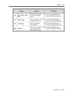
Output 

Refers to 

Meaning 

YB  Tower Light – Green 

(RY7) 

Output to turn on Relay 7 

(for the green Beacon 

Light) 

: Currently triggered/activated 

: Not currently triggered/activated


YC  H-Perf Trigger 

Output to cycle an optional 

Horizontal Perforator 

: Currently triggered/activated 

: Not currently triggered/activated


YD  Print Trigger 

Output to operate an 

optional Printer 

: Currently triggered/activated 

: Not currently triggered/activated


Y200  Aux Belt 

Output to turn on Relay 10 

(for the Auxiliary Belts / 

Bottle Holding Devices) 

: Currently triggered/activated 

: Not currently triggered/activated


Summary of Contents for LX-150

Page 1: ...LX 150 Shrink Sleeve Label Applicator User Guide ...

Page 2: ...2 Abbreviations 4510001 REV B 220620 ...

Page 3: ...202022 P N 4510001 Rev B Copyright and Trademarks Copyright 2022 American Film and Manufacturing All rights reserved All trademarks and brand names are the property of their respective owners AFM 7041 Boone Avenue North Brooklyn Park MN 55428 Phone 714 974 9006 Fax 763 795 8867 www afmsleeves com ...

Page 4: ...4 Abbreviations 4510001 REV B 220620 ...

Page 5: ...Equipment 20 Turn Bar 20 Auxiliary Belt Bottle Holding Device 21 Preheat Gun Assembly 22 T Perforator 23 Vertical Perforator 24 Irregular Timing Screw 25 Dual Timing Screw 25 Customer Supplied Equipment 26 Introduction 27 General Overview 27 UR 1 Detailed Overview 28 LX 150 Detailed Overview 29 Mandrel 29 Cutter Assembly 30 Chassis 31 Electronics Cabinet 40 System Specifications 41 Cutter Assembly...

Page 6: ... the LX 150 48 Installing the UR 1 50 Installing the Cutter Assembly 53 Installing the Mandrel 56 Fine Tuning the LX 150 Position 60 Alternate Positioning 63 Installing the Timing Screw Assembly 65 Installing the Brushdown Assemblies 70 Attaching the Power Plug 74 Properly Set Up System 75 Software 77 Software Map 77 Common Buttons 79 Other Screen 80 Alarm Message Screen 81 Knife Offset Screen 83 ...

Page 7: ...ce No Catch Mark 108 Notice Cutter Can t Find Its Home 109 Notice Cutter Need Positioning 110 Common Procedures 111 Tensioner Unlocking Adjusting Locking 111 Film Drive Wheels Unlocking Adjusting Locking 112 Support Wheels Unlocking Adjusting Locking 113 Applicator Wheels Unlocking Adjusting Locking 115 Setup 117 Positioning the Cutter Blades 117 Installing the Film 119 Threading the Film 121 Fine...

Page 8: ... Timing Belt 166 Replacing the Timing Belt and Cutter Drive Belt 167 Replacing the Cutter Bearings 169 Greasing the Shafts of the Head Height Adjust 172 Greasing the Shafts of the Applicator Wheel Vertical Adjust 173 Greasing the Shafts of the Film Drive Wheel Adjusts 174 Greasing the Shafts of the Support Wheel Adjusts 175 Replacing the Film Drive Wheels 176 Replacing the Support Wheels 177 Repla...

Page 9: ... 220V 200 LX150N J001 480V 201 LX150N J002 480V 202 LX150N J003 480V 203 LX150N J004 480V 204 LX150N J005 480V 205 LX150N J006 480V 206 LX150N J007 480V 207 LX150N J008 480V 208 LX150N J009 480V 209 LX150N J010 480V 210 LX150N J011 480V 211 LX150N J012 480V 212 LX150N J013 480V 213 LX150N J014 480V 214 LX150N J015 480V 215 LX150N J016 480V 216 Diagrams and Parts Lists 217 UR 1 217 Dancer Assembly ...

Page 10: ...unt 234 Support and Film Drive Wheel Assemblies 235 400mm Timing Screw Assembly 238 Video Library 241 Instructional Videos 241 Capabilities 242 Warranty Statement 243 Limitations 243 Repairs 243 Shrinking Quality 243 Shipping Policy 243 Exclusions 243 Warranty Verification 243 Warranty Eligibility 244 Limited Warranty 244 Disclaimer of Damages 244 Technical Support 245 ...

Page 11: ...nal Protective Equipment CL Cut Length PREV Previous cm Centimeters Psi Pounds per Square Inch DECEL Decelerator PVC Polyvinyl Chloride DET Detected R Right E Stop Emergency Stop REV Reverse ENT Enter RPM Revolutions per Minute F Fahrenheit RST Reset FWD Forward sec Second GND Ground SEL Select HMI Human Machine Interface Semi Auto Semi Automatic Hz Hertz Servo Servomechanism or servomotor I O Inp...

Page 12: ...12 Abbreviations 4510001 REV B 220620 ...

Page 13: ...ipment Failure to follow these instructions may result in damage to the equipment fire serious personal injury or death Before turning on the LX 150 always ensure that o All necessary accessories are properly connected o All Rollers spin smoothly without obstruction o The Conveyor Belt is free of obstruction and operating properly o The path for the label film including the Mandrel is clean and fr...

Page 14: ...ctual emergencies Routine use of the E Stop Button can damage the machine and void the warranty Service and maintenance beyond what is described in this User Guide should be performed by a trained and qualified technician If in doubt contact AFM or your authorized distributor Use proper lifting techniques when lifting heavy rolls of labels This machine is protected by hardware Master Control Relay...

Page 15: ...sult in death or serious injury WARNING Indicates a hazardous situation which if not avoided could result in death or serious injury CAUTION Indicates a hazardous situation which if not avoided could result in minor or moderate injury ATTENTION Indicates a hazardous situation which if not avoided could result in property damage only ...

Page 16: ...ent PPE including Cut Resistant Gloves Electrical Hazard No user serviceable parts inside Dedicated circuit recommended Check polarity Electrical Ground Hazard Ensure that unit is properly grounded Fume Hazard Some fumes may be a health hazard with prolonged exposure Ensure that the area has proper ventilation Pinch Hazard Keep hands clear Crush Hazard Keep hands clear Fire Hazard Do not tamper wi...

Page 17: ... Round Mandrel Conveyor Braces Cutter Assembly Toolkit The LX 150 is shipped assembled and tested When unpacking the shipping carton verify that the contents are complete and in proper condition If items are missing or damaged contact your AFM distributor immediately AFM LX 150 System UR 1 Unwind System LX 150 Mandrel Cutter Assembly Timing Screw Assembly Brushdown Assembly Tool Kit AFM 4510001 00...

Page 18: ...om the LX 150 and guides bottles into the machine at a consistent evenly spaced rate A 15 75 400mm or 31 50 800mm Timing Screw Assembly is included as a standard part of LX 150 Shrink Sleeve Label Applicator Each customer s Timing Screw is made to fit their specific bottle with a small range of tolerance Bottle diameter dictates the pocket size and pitch of a Timing Screw AFM can custom build addi...

Page 19: ...yor immediately downstream from the LX 150 After the bottle has passed through the LX 150 the tendrils of the Brushdown Assembly brush softly down over the sides of the bottle to ensure that the bottom edge of the label is flush with the Conveyor surface or flush with the Auxiliary Belts Bottle Holding Devices if used before the bottle enters the Heat Shrink Tunnel Brushdown Assembly AFM 4510001 0...

Page 20: ...d if the UR 1 is positioned at a 90 angle to the LX 150 rather than in the recommended position at the Conveyor directly upstream from the LX 150 The Turn Bar attaches to the top of the LX 150 near the Dancer and can be used to redirect the label film at a 90 angle after it has left the UR 1 and enters the LX 150 Turn Bar Turn Bar Turn Bar Top View LX 150 UR 1 AFM 4510001 00035 01 AFM 4510001 0003...

Page 21: ...ent seal is being applied to the top of a bottle an Auxiliary Belt Bottle Holding Device may be needed to stop the label before it reaches the bottom of the bottle Auxiliary Belts Bottle Holding Devices go on either side of the Conveyor Belt near the Mandrel and touch the sides of the passing bottles to block the paths of the labels as they slide down the length of the bottles Auxiliary Belt Bottl...

Page 22: ...n using an Auxiliary Belt Bottle Holding Device a Preheat Gun Assembly mounted near the end of the Belt is recommended to provide flash shrinking to hold the label in position before it reaches the Heat Shrink Tunnel Preheat Gun Assembly AFM 4510001 00036 01 AFM 4510001 00040 01 ...

Page 23: ...Part Number 4502204 A T Perforator can be used to perforate in the patterns below to provide tamper evidence or to facilitate removal by the customer A tool change is needed to change the pattern of the perforation T Perforator AFM 4510001 00041 01 ...

Page 24: ...24 Equipment 4510001 REV B 220620 Vertical Perforator Part Number 4502093 A Vertical Perforator is used to make vertical label perforations as shown below Vertical Perforator AFM 4510001 00325 01 ...

Page 25: ...so ensure that they are correctly aligned to receive a label from the Mandrel Dual Timing Screw A Dual Timing Screw is used for irregularly shaped containers square rectangular oval or when using labels to bundle multiple containers at once VIDEO Multi Pack Sleeving To see a video of multi pack sleeving using a Dual Timing Screw click this link https youtu be wCvL Gp2wTo Or scan the QR code at rig...

Page 26: ...ipment 4510001 REV B 220620 Customer Supplied Equipment Customers are responsible for supplying additional equipment Including Cut Resistant Safety Gloves Safety Shoes Safety Glasses All other safety clothing ...

Page 27: ...l film enters the Dancer which evens out the tension on the label film From the Dancer the label film goes over the Top Rollers down onto the Mandrel Fin and down the length of the Mandrel As the film passes through the Cutter Assembly it is cut to the correct label size and then the Applicator Wheels at the bottom of the Mandrel shoot the cut label down onto the passing bottle The LX 150 only app...

Page 28: ...ol Box allowing the user to select which Film Spool should be feeding film and the rotation direction of that Film Spool Below the Film Spools is a Splicing Table where splicing tape can be used to attach the end of the first film roll to the beginning of the second film roll eliminating the need to thread film through the entire system every time a roll of film runs out UR 1 Film Spool 2 Splicing...

Page 29: ...port Bearings holding the Mandrel in place The Film Drive Wheels contact the Mandrel s Film Drive Bearings similarly helping to hold the Mandrel in place and also advancing the label film down the length of the Mandrel Body one label length at a time As the film passes by the Cutter Notch information from the Print Reading Sensor triggers the Cutter Blades to rotate through the Cutter Notch cuttin...

Page 30: ...le in the Cutter Assembly The Cutter Home Position Sensor inside the Chassis must see the Cutter Home Tab on the Cutter Drive Pulley for the LX 150 to operate When the cut mark in the label material passes across the Cutter Notch in the Mandrel the Print Reading Sensor triggers the Blade Assemblies to quickly rotate the Blades 360 through the Cutter Notch cutting through the label film Cutter Guar...

Page 31: ... spring loaded The label film winds through them as it enters the LX 150 evening out the tension in the film The Film Supply Sensor mounted at the bottom of the Dancer adjusts the speed of the unwind based on the distance between the Sensor and the innermost bottom Roller Film Supply Sensor AFM 4510001 00063 01 The Top Roller Bar ensures that the path of the label film is straight down onto the Ma...

Page 32: ...o communicates with the Cutter Assembly to tell it when to cut the film AFM 4510001 00109 02 Print Reading Sensor Two sets of Support Wheels Upper and Lower hold the Mandrel in place Each set can be adjusted independently To adjust each set their Support Wheel Lock must first be loosened Turning the Support Wheel Adjust moves them in or out from the Mandrel Once in position the Support Wheel Lock ...

Page 33: ...ngth of the Mandrel The Upper and Lower Film Drive Wheels are adjusted together To adjust them the Film Drive Wheel Lock must first be loosened and then the Film Drive Wheel Adjust can be turned to move the Wheels in or out from the Mandrel Once in position the Film Drive Wheel Lock must be tightened again to secure them in place Film Drive Wheels Film Drive Wheel Adjust Film Drive Wheel Lock AFM ...

Page 34: ...ng the length of the Mandrel To move the Applicator Wheels in or out from the Mandrel the Applicator Wheel Horizontal Locks must be loosened and then the Applicator Wheel Horizontal Adjust can be turned until the Wheels are just touching the Applicator Bearings in the Mandrel Once the Applicator Wheels are in position the Applicator Wheel Vertical Lock and Applicator Wheel Horizontal Lock must be ...

Page 35: ...t Arms Cutter Home Position Sensor The Cutter Support Arms on either side of the Cutter Assembly hold the Cutter Assembly in place AFM 4510001 00058 01 Cutter Support Arms The Cutter Home Position Sensor located just above the Cutter Drive Pulley ensures that the Cutter Assembly and Cutter Blades are properly in position AFM 4510001 00150 01 Cutter Home Position Sensor AFM 4510001 00116 01 ...

Page 36: ... Fail Sensor Eye which is located in the back of the Chassis immediately below the Cutter Assembly If the Sensor Eye detects label film for too long a time it may be a sign that the label film has jammed and the Application Fail Sensor Amplifier sends a signal to stop production AFM 4510001 00101 01 Application Fail Sensor Amplifier AFM 4510001 00102 01 AFM 4510001 00058 01 Application Fail Sensor...

Page 37: ...licator Wheel to shoot a label down onto the bottle AFM 4510001 00120 01 AFM 4510001 00121 01 Work Detective Sensor Work Detective Sensor Reflector Slider The Head Height Adjustment Crank is the large crank on the right side of the LX 150 Turning it enables the entire Head Assembly including the Sensors Wheels Mandrel and Cutter Assembly to be moved up or down as a single unit The Head Assembly mo...

Page 38: ...neral status of the system Red Light There is a fault somewhere in the system and the machine has stopped Yellow Light Warning the Doors are open or the film is low Green Light The system is operating and all conditions are good White Light The system is powered on and ready to use AFM 4510001 00056 01 Alarm Beacon ...

Page 39: ...e and enables users to input commands and settings Power Switch Powers the system on or off Start Button Starts the machine and connected peripherals Stop Button Stops the machine and connected peripherals Emergency Stop Button Immediately stops the machine and connected peripherals sounds an alarm and brings up an alarm screen on the Touchscreen Fault Reset Button Enables any fault alarm to be tr...

Page 40: ...hes to open the Door of the Cabinet The Electronics Cabinet should remain closed during operation and should only be opened by a trained technician WARNING Electric shock risk The Electronics Cabinet should only be opened by a trained technician Electronics Cabinet Main Power Switch AFM 4510001 00053 01 AFM 4510001 00065 01 AFM 4510001 00054 01 AFM 4510001 00106 01 Brushdown Outputs Auxiliary Belt...

Page 41: ...th 1 58 9 84 40 250 mm Film Thickness 0 0014 0 027 0 035 0 07mm Film Material OPS PVC PET Speed will vary with the shape and types of items thickness and length of shrinkable film Maximum speed will be determined by actual running conditions NOTE Formula for calculating correct film lay flat width cylindrical bottles Bottle Diameter 2 4 mm x 1 57 NOTE Bottles in irregular shapes square rectangular...

Page 42: ...eing used Custom sized Cutter Assemblies tailored to specific needs can also be built by AFM upon request Cutter Size Part Number Approximate Bottle Diameter Label Lay Flat Width Small 4 blade 4500462 Ø 0 98 2 76 Ø 25 70 mm Ø 1 89 4 53 Ø 48 115 mm Medium 5 blade 4505152 Ø 1 57 4 72 Ø 40 120 mm Ø 3 07 6 89 Ø 78 175 mm Large 6 blade 4505153 Ø 3 54 5 91 Ø 90 150 mm Ø 5 51 9 45 Ø 140 240 mm ...

Page 43: ...Introduction 43 4510001 REV B 220620 System Dimensions UR 1 Unwind System Front View Top View Side View ...

Page 44: ...44 Introduction 4510001 REV B 220620 LX 150 Shrink Sleeve Label Applicator Top View Front View Upstream View Downstream View ...

Page 45: ... correct position to be labeled and unpredictable movements are minimized Incorrect or inconsistent product handling will cause labeling problems maintenance problems and could lead to equipment damage The customer is responsible for maintaining proper material handling equipment Additionally the Conveyors themselves should be stable should be properly maintained smooth running Chain for example a...

Page 46: ...oid interfering with the Conveyor flow In this case a Turn Bar will be needed to redirect the film into the LX 150 see Turn Bar on page 20 Mandrel Position The center line of the Conveyor will need to run beneath the central axis of the Mandrel see Fine Tuning the LX 150 Position on page 60 Maintenance Access When planning the installation allow for easy access to the Front Door and Electronics Ca...

Page 47: ...on on it Take reasonable steps to reduce humidity in the work area Traffic Patterns Careless positioning can result in damage to the LX 150 or UR 1 An example would be positioning the machines where they can be accidentally knocked by a Forklift or similar placement in an area of predictable traffic Keep the LX 150 and UR 1 away from known traffic paths ATTENTION Locate the LX 150 and UR 1 away fr...

Page 48: ...0 Hz grounded Allen Wrench included in Tool Kit Code compliant 3 phase 220V 50 60 Hz grounded AC power supply Sturdy Ladder if installing Turn Bar Installing the LX 150 Items Needed to Install the LX 150 Forklift At least 3 people to move the machine Large Crescent Wrench To Install the LX 150 Find a suitable location for the system a Near a code compliant 3 phase 220V 50 60 Hz grounded power supp...

Page 49: ...lled later The Conveyor should run through the sides of the LX 150 exiting the side where the HMI is Remove the plastic film covering from the LX 150 Positioning the LX 150 View from Above Conveyor LX 150 HMI Conveyor Product Flow Heat Shrink Tunnel UR 1 Positioning the LX 150 View from Front Conveyor LX 150 HMI Conveyor Product Flow Heat Shrink Tunnel UR 1 ...

Page 50: ... https youtu be shn5o7MZXbM Or scan the QR code at right using the camera app on your mobile device Time 1 41 1 49 Items Needed to Install the UR 1 Forklift Level At least 3 people to move the machine Laser Level Large Crescent Wrench Ruler To Install the UR 1 Have a licensed Forklift operator remove the UR 1 from its shipping container Move the UR 1 generally into position upstream from the LX 15...

Page 51: ...f the width of a roll of label film as shown below Measure that same distance from the Rear Plate on a Spool on the UR 1 Positioning the UR 1 View from Front LX 150 UR 1 Heat Shrink Tunnel Fine Tuning the UR 1 Position View from Above Half the Width of a Label Roll Centerline of Conveyor Splicing Table Rear Plate ...

Page 52: ...ligns with the centerline of the Conveyor Belt Place the Level on the Splicing Table and use the Crescent Wrench to adjust the Feet of the UR 1 so that the Splicing Table is level Making sure that the UR 1 is perfectly parallel to the Conveyor use the Conveyor Mounts to secure the UR 1 to the Conveyor in its current position ...

Page 53: ...ter Adjustments To see a video of this procedure click this link https www youtube com watch v 036vSOgbL0A Or scan the QR code at right using the camera app on your mobile device Time 2 20 2 52 Needed to Install the Cutter Assembly Allen Wrench included in Tool Kit Cut Resistant Work Gloves To Install the Cutter Assembly Be sure that the LX 150 is turned off and unplugged from any power source Ope...

Page 54: ...sen the Tensioner Lock on the right side of the Cutter Support Arm Loop the Cutter Drive Belt around the Cutter Drive Pulley in the inside right corner of the Cutter Assembly The tension on the Cutter Drive Belt should be very tight Cutter Support Arm Screws Beneath Cutter Support Arms Screws at Ends of Cutter Support Arms Cutter Guard Cutter Assembly Cutter Support Arm Cutter Assembly Loosening t...

Page 55: ...Installation 55 4510001 REV B 220620 While pulling the Tensioner firmly toward the front of the LX 150 tighten the Tensioner Lock The Mandrel can now be installed see Installing the Mandrel on page 56 ...

Page 56: ... hold the Mandrel firmly by hand when installing it will result in the Mandrel falling potentially damaging it and the LX 150 and voiding the warranty VIDEO Installing the Mandrel To see a video of this procedure click this link https youtu be _I6lIKRz6qQ Or scan the QR code at right using the camera app on your mobile device Needed to Install the Mandrel Cut Resistant Work Gloves To Install the M...

Page 57: ... the Mandrel down through the Wheel Assemblies and Cutter Assembly When the Mandrel is in the correct position a The Print Reading Sensor should align with the slot in the Mandrel Fin The position of the Print Reading Sensor can be adjusted later if needed b The Film Drive Wheels should align with the Film Drive Bearings on the sides of the Mandrel c The Support Wheels should align with the Suppor...

Page 58: ... the Film Drive Bearings on the Mandrel and then lock them in position page 112 ATTENTION The Film Drive Wheels should be tight enough to consistently advance the label film Tightening them too much can damage the film and potentially pull the Mandrel out of the Support Wheels hold This can damage the Mandrel the Cutter Assembly and the LX 150 and void the warranty If needed move the Applicator Wh...

Page 59: ... ATTENTION The Applicator Wheels should only be tight enough to advance the label film Tightening them too much can potentially damage the Wheels Mandrel and Applicator Assembly and can void the warranty Close the Front Door of the LX 150 ...

Page 60: ...ast 3 people to move the machine Large Crescent Wrench Level Laser Level Tape Measure To Fine Tune the LX 150 Position Align the center line of the Mandrel with the center line of the Conveyor a Place a sample bottle in the center of the Conveyor Belt directly below the Mandrel b Use the Tape Measure to place the Laser Level precisely in the center of the Conveyor downstream from the LX 150 and ai...

Page 61: ...Wrench to turn the Nut on each Leg of the LX 150 so that the Feet so that the unit can no longer roll on the Casters b Using a Level and the Crescent Wrench fine tune the height of each Leg and level the machine c Attach the Conveyor Braces to secure the Conveyor to the LX 150 and maintain the correct centerline position Bottle Mandrel Position View from Downstream Side Conveyor Mandrel Central Ax...

Page 62: ...e bottle The distance should be approximately half the length of the labels that will be applied as shown in the Mandrel Position diagram on the previous page Turn the Laser Level off but leave it in position It will be used when installing the Timing Screw AFM 4510001 00090 01 AFM 4510001 00103 01 Conveyor Brace Conveyor Brace Head Height Adjustment Crank ...

Page 63: ...lled Items Needed to Perform Alternative Positioning Sturdy Ladder Large Crescent Wrench Total of at least 3 people to move the UR 1 Level Laser Level Large Crescent Wrench To Perform Alternative Positioning Mount the Turn Bar to the top left upstream side of the LX 150 so that the Turn Bar extends horizontally at approximately a 45 angle above the Dancer as shown Installing the Turn Bar View from...

Page 64: ...e centerline of a roll of label film on the Film Spool points directly at spot shown by the laser level Place the Level on the Splicing Table and use the Crescent Wrench to adjust the Feet of the UR 1 so that the Splicing Table is level Fine Tuning the Alternative UR 1 Position View from Above LX 150 Heat Shrink Tunnel Turn Bar Centerline of Label Film UR 1 Conveyor Laser Level Centerline of Conve...

Page 65: ...ideo of this procedure click this link https youtu be shn5o7MZXbM Or scan the QR code at right using the camera app on your mobile device Time 1 50 2 12 VIDEO Machine Adjustments and Fine Tuning To see a video of this procedure click this link https youtu be Q3k865kFjmw Or scan the QR code at right using the camera app on your mobile device Time 0 00 1 01 Items Needed to Install the Timing Screw A...

Page 66: ...220620 AFM 4510001 00177 01 Positioning the Timing Screw View from Front Timing Screw LX 150 HMI Conveyor Product Flow Heat Shrink Tunnel UR 1 Positioning the Timing Screw View from Above LX 150 Heat Shrink Tunnel UR 1 Timing Screw ...

Page 67: ... from the Timing Screw Sensor positioned in such a way to be hit by the beam of the Timing Screw Sensor Fine Tune the Position of the Timing Screw a With the Laser Level in the center of the Conveyor turn the Laser Level on b Place a sample bottle in one of the pockets of the Screw AFM 4510001 00136 01 Mounting the Timing Screw Sensor and Reflector Timing Screw Assembly Motor Timing Screw Sensor A...

Page 68: ...or until the laser beam is pointing at the center axis of the bottle As shown below Plug the Cable from the Timing Screw into the Power Box Attach the Junction Box to the Conveyor Plugging in the Timing Screw Assembly Crank AFM 4510001 00172 01 AFM 4510001 00176 01 Laser on Center Axis of Bottle Plugging in the Timing Screw Assembly AFM 4510001 00178 01 Junction Box Cable Timing Screw Power Cable ...

Page 69: ... of the Timing Screw s Power Cable into the Junction Box and plug the other end into the appropriate Power Port on the upstream side of the LX 150 s Electronics Cabinet Plugging in the Timing Screw Assembly Timing Screw Power Port AFM 4510001 00106 01 ...

Page 70: ...nd upstream from the Heat Shrink Tunnel VIDEO Equipment Setup To see a video of this procedure click this link https youtu be shn5o7MZXbM Or scan the QR code at right using the camera app on your mobile device Time 2 12 1 52 VIDEO Machine Adjustments and Fine Tuning To see a video of this procedure click this link https youtu be Q3k865kFjmw Or scan the QR code at right using the camera app on your...

Page 71: ...nto a Mount The Brushdown s Motor should be on the upstream side and the bristles should be exposed to the centerline of the Conveyor Positioning the Brushdown Assemblies View from Front Timing Screw LX 150 HMI Brushdown Assembly Product Flow Heat Shrink Tunnel UR 1 Mounting the Brushdown Assemblies AFM 4510001 00179 01 AFM 4510001 00180 01 Brushdown Mount Brushdown Motor ...

Page 72: ...em in position Attach the Control Box to the most accessible Mount Brushdown Locks AFM 4510001 00181 01 Properly Attached Brushdown Assemblies AFM 4510001 00033 01 AFM 4510001 00030 01 Attaching the Control Box to the Mount AFM 4510001 00082 01 Brushdown Control Box Brushdown Mount Brushdown Motor ...

Page 73: ...EV B 220620 Plug the Brushdown Assemblies Power Cables into the appropriate Power Ports on the downstream side of the LX 150 s Electronics Cabinet Plugging in the Brushdown Assemblies AFM 4510001 00054 01 Brushdown Power Ports ...

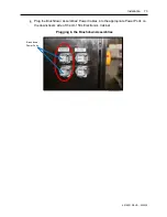
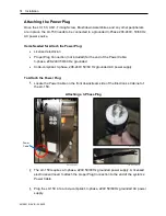
Page 74: ...phase 208 240V 50 60 Hz grounded Code compliant 3 phase 208 240V 50 60 Hz grounded AC power supply To Attach the Power Plug Locate the Power Cable on the front downstream side of the Electronics Cabinet of the LX 150 The LX 150 requires a 3 phase 220V 50 60 Hz grounded power supply A licensed electrician will need to attach the proper Plug Connection to the end of the system s Power Cable Plug the...

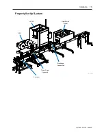
Page 75: ...Installation 75 4510001 REV B 220620 Properly Set Up System UR 1 Conveyor LX 150 Heat Shrink Tunnel Timing Screw Assembly Brushdown Assemblies ...

Page 76: ...76 Installation 4510001 REV B 220620 ...

Page 77: ...digital version of this User Guide each screen name in the map links to a section explaining the function of the screen Other Screen p 80 Alarm Message p 81 History Message p 82 Knife Offset p 83 PLC Input 1 PLC Input 2 p 84 PLC Output 1 PLC Output 2 p 86 PLC I O Monitor p 88 Parameter Setting p 89 Parameter Setting Screen 1 Cut Feed Procedure Setting Product Selection Scan Jump Motor Parameter 1 ...

Page 78: ... 41 80 Work Screen p 96 Product Target Setting p 98 Alarms Notice Reached Preset Target p 99 Notice Application Fail p 100 Notice Emergency Stop p 102 Notice Please Close the Door First p 103 Notice Offset Position Is Not Reached p 104 Notice Pulse Feedback Signal Abnormalities p 105 Notice Low Film p 106 Notice Film Empty p 107 Notice No Catch Mark p 108 Notice Cutter Can t Find Its Home p 109 No...

Page 79: ...hen an alarm is triggered this button turns the Buzzer off Fault Reset Button When an alarm is triggered this button resets the alarm to be able to be triggered again This button does not resolve the problem that led to the alarm being triggered Previous Button Advances to the previous screen on the same level in the Software Map Next Button Advances to the next screen on the same level in the Sof...

Page 80: ...20620 Other Screen Accessed by pressing the Other Tab at the top This is a portal through which the Alarm Message Screen the Knife Angle Adjust Screen the PLC I O Monitor Screens and the Parameter Setting Screens can be accessed ...

Page 81: ...hat alarm and whether it has been successfully cleared History Button Accesses the History Message Screen displaying a log of the alarms that have been triggered on the machine Buzzer Stop Button Turns off the Buzzer Fault Reset Button Resets the fault alarm to be able to be triggered again This button does not resolve the problem that led to the alarm being triggered ...

Page 82: ...ays the current date in month day year format in the upper right part of the screen HHMMSS Display Displays the current time in hours minutes seconds format in the upper right part of the screen Trigger Displays when an alarm was triggered Message Displays what the alarm is Recovery Displays when an alarm was successfully cleared Clear Button Permanently deletes the selected fault from the log ...

Page 83: ... be corrected Knife Offset Field Enters an angle to recalibrate the home position for the blades relative to the Cutter Home Tab In the example above Position A above shows the Blades in their correct home position relative to the Cutter Home Tab In Position B the Blades are 40 out of alignment from their home position By entering 40 in the Knife Offset Field pressing the Set Button and pressing a...

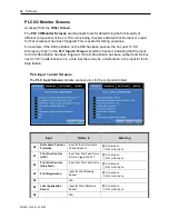
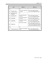
Page 84: ...top Button has been pushed and the box next to X8 is not checked it is a clue that there may be a malfunction in the input for the E Stop Button PLC Input 1 and 2 Screens The PLC Input Screens indicate an input error for the component listed Input Refers to Meaning X0 Knife Home Position Proximity Input for the Cutter Home Position Sensor Currently on Not currently on X1 Print Function Use HSC Inp...

Page 85: ... Start Button Input for the Start Button on the HMI Currently triggered activated Not currently triggered activated XC Stop Button Input for the Stop Button on the HMI Currently triggered activated Not currently triggered activated XD Safety Door Input for the Front Door Currently triggered activated the machine sees the Front Door as closed Not currently triggered activated the machine sees the F...

Page 86: ...1 for the Applicating Motor Currently triggered activated Not currently triggered activated Y5 Buzzer RY2 Output to turn on Relay 2 for the Buzzer Currently triggered activated Not currently triggered activated Y6 Print Function Use Stop Feed Output to the Film Feed Servo Currently triggered activated Not currently triggered activated Y7 Brush Output to turn on Relay 3 for the Brushdown Assemblies...

Page 87: ...YC H Perf Trigger Output to cycle an optional Horizontal Perforator Currently triggered activated Not currently triggered activated YD Print Trigger Output to operate an optional Printer Currently triggered activated Not currently triggered activated Y200 Aux Belt Output to turn on Relay 10 for the Auxiliary Belts Bottle Holding Devices Currently triggered activated Not currently triggered activat...

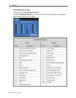
Page 88: ...1 Print Function Use HSC Y1 Cutter Dir X2 Print Function Use Stop Feed Y2 Feed Pulse X3 Print Registration Y3 Feed Dir X4 N A Y4 Working RY1 X5 Label Application Sensor Y5 Buzzer RY2 X6 N A Y6 Print Function Use Stop Feed X7 N A Y7 Brush X8 Emergency Stop Y8 Tower Light Yellow RY4 X9 Film Accumulator Ready Det Y9 Film Supply Motor RY5 XA Application Fail YA Timing Screw Motor RY6 XB Start Button Y...

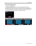
Page 89: ...d screens whose parameters are either set up at the factory or set up during installation Each parameter describes a specific aspect of how the machine needs to function for the label film used and the containers being labeled For assistance in adjusting any parameters please contact your trained and authorized AFM Distributor or AFM Service Engineer ...

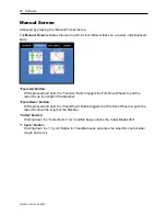
Page 90: ...n triggers the Film Drive Wheels to pull the label film up the length of the Mandrel Feed Down Button While pressed and held the Feed Down Button triggers the Film Drive Wheels to push the label film down the length of the Mandrel Cutter Button Holding down the Cutter Button for 5 audible beeps rotates the Cutter Blades 360 1 Cycle Button Holding down the 1 Cycle Button for 5 audible beeps advance...

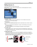
Page 91: ...nsor No Cuts are triggered each time the label film has advanced a specified distance Cut Length Field Sets the length of a label A value must be entered in this field regardless of which kind of cut trigger was selected in Print Cut Length tells the LX 150 how long to expect a label to be Select Set to accept the value Print Reg Dwell Field This field is for use when Print is set to Yes It adjust...

Page 92: ... a passing bottle Values are entered using the Number Buttons below the Application Delay field The negative values decrease the delay time causing the label to be applied sooner The positive values increase the delay time causing the label to be applied later Select Set to accept the value Band Release Delay Correctly Timed Labels Labels Being Applied Too Late Band Release Delay value should be d...

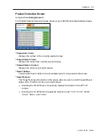
Page 93: ...y selected recipe Product Name Column Displays the name of up to eight recipes Select Button Touching the Select Button to the immediate right of a recipe selects that recipe Page Buttons The Page Buttons at the bottom of the screen allow the user to scroll through different pages each of which can have up to eight recipes Selecting the 25 32 Button for example displays the Screen for the 25th 32n...

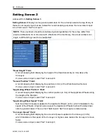
Page 94: ...sor Position Field A record keeping field displaying the position in mm of the Work Detective Sensor If a new value is input select Set to accept it Applicating Wheel Position Field A record keeping field displaying the vertical position in mm of the Applicator Wheels along the length of the Mandrel If a new value is input select Set to accept it Applicating Wheel Speed Field Sets the amount of po...

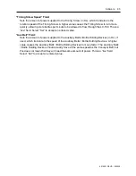
Page 95: ... Select Set to accept an entered value Aux Belt Field Sets the amount of power supplied to the Auxiliary Belts Bottle Holding Devices in Hz if used which translate to the speed of the Auxiliary Belts Bottle Holding Devices A higher value causes the Auxiliary Belts Bottle Holding Devices to move faster The Auxiliary Belts Bottle Holding Devices should visually move at the same speed as the Conveyor...

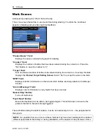
Page 96: ...ays the Product Target Setting Screen Select Set to accept the value in the field BPM Field Displays real time information on the rate at which bottles are being labeled in bottles per minute Alarm Message Field Displays current information on any faults that have occurred Buzzer Stop Button Turns off the Buzzer Fault Reset Button Resets the fault alarm to be able to be triggered again This button...

Page 97: ...current run The Horizontal Perforator will start when the Start Button on the HMI is pressed Printer Button Activates an optional Printer if relevant so that it can be used during the current run The Printer will start when the Start Button on the HMI is pressed Brush Button Activates the Brushdown Assemblies so that they can be used during the current run The Brushdown Assemblies will start when ...

Page 98: ...ting Screen Accessed from the Work Screen The Product Target Setting Screen is for setting how many bottles are to be labeled during the current run Target Field Sets the number of bottles to be labeled in the current run Select Set to accept the value ...

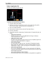
Page 99: ...tinue labeling Notice Reached Preset Target Alerts the user that the target number of bottles has been labeled To Address the Fault and Resume Labeling Press the Buzzer Stop Button Enter a new value typically 0 into the Counter Field Enter a new value into the Target Field for the number of bottles to be labeled during the next labeling run Press the Faut Reset Button Press the Exit Button ...

Page 100: ... is too large or small see System Specifications on page 41 o Inappropriate Label Length The labels being applied are longer or shorter than the acceptable range for the machine see System Specifications on page 41 o Incorrect Head Height The head height is too high or too low The bottom of the Mandrel should be approximately half a label length from the tops of passing bottles see Head Height Adj...

Page 101: ...o the film cannot move through or the Film Drive Wheels are too far from the Applicator Bearings so they not advancing the film with precision see Film Drive Wheels Unlocking Adjusting Locking on page 112 o Incorrect Applicator Wheel Position The Applicator Wheels are too far from the Applicator Bearings so they are occasionally slipping against the label film rather than pushing it see Applicator...

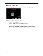
Page 102: ... the Fault and Resume Labeling Press the Buzzer Stop Button Determine why the Emergency Stop Button was pressed If a safety hazard exists thoroughly address and eliminated the safety hazard Reset the physical Emergency Stop Button on the HMI by turning it clockwise After the issue has been resolved press the Faut Reset Button Press the Exit Button ...

Page 103: ...st The Front Door is open As a safety feature it must be closed when the LX 150 is operating To Address the Fault and Resume Labeling Press the Buzzer Stop Button Close the Front Door After the issue has been resolved press the Faut Reset Button Press the Exit Button ...

Page 104: ...e not too far from the Film Drive Bearings in the Mandrel If they are too far from the Bearings they will not properly grip the film and may not advance the film with precision If needed adjust the Film Drive Wheels see Film Drive Wheels Unlocking Adjusting Locking on page 112 On Setting Screen 1 confirm that the Cut Length is within the acceptable range 40 250 mm Assigning too short a Cut Length ...

Page 105: ...es An error has taken place with the Feed Servo Drive To Address the Fault and Resume Labeling Press the Buzzer Stop Button Contact AFM Technical Support at 714 974 9006 or info afmsleeves com After the issue has been resolved press the Faut Reset Button Press the Exit Button ...

Page 106: ...nt film roll is running low To Address the Fault and Resume Labeling Press the Buzzer Stop Button Load a new film roll on the other Film Spool see Installing the Film on page 119 After the new roll has been loaded press the Faut Reset Button Press the Exit Button Watch the film roll closely and be prepared to stop the machine before the current roll runs out completely so that splice the beginning...

Page 107: ...lt and Resume Labeling Press the Buzzer Stop Button If possible splice the beginning of the new label film roll onto the end of the old roll see Switching Film Rolls on page 141 If the film roll has completely run out the label film from the new roll may need to be threaded through the system see Threading the Film on page 121 and Fine Positioning the Film for Cutting on page 128 When the film has...

Page 108: ...lm path for kinks wrinkles tangles twisting obstructions unusual wear etc and correct any issues found Check that the Film Drive Wheels are not too tight against the Film Drive Bearings impairing the film s ability to move through easily or that the Film Drive Wheels are not too far from the Applicator Bearings preventing them from advancing the film with precision If needed adjust the position of...

Page 109: ...r Home Tab is directly below the Cutter Home Position Sensor Underneath the Cutter Assembly look at the position of the Cutter Blades and estimate the angle that would return them to their home position Close the Front Door Select the Other Screen Tab and go to the Knife Offset Screen Enter the estimated angle in the Knife Offset Field and press the Set Button to accept it Repeat steps 3 6 until t...

Page 110: ... Fault and Resume Labeling Press the Positioning Button The Cutter Blades will rotate to their home position Confirm that the Cutter Blades are in their proper home position by opening the Front Door and looking underneath the Cutter Assembly Close the Front Door If the Cutter Blades are out of alignment follow the instructions for Notice Cutter Can t Find Its Home on page 109 Press the Exit Butto...

Page 111: ...ion During all of these procedures unless otherwise stated the UR 1 and LX 150 should be turned off Tensioner Unlocking Adjusting Locking The Tensioner on the side of the right Cutter Support Arm ensures that the Cutter Drive Belt puts the right amount of pressure on the Cutter Drive Pulley To Adjust the Tensioner Loosen the Tensioner Lock by turning it counterclockwise Push the Tensioner toward t...

Page 112: ...el Lock by turning it counterclockwise ATTENTION Attempting to adjust the Film Drive Wheels when they are locked can damage the LX 150 and void the warranty Holding the Mandrel with one hand turn the Film Drive Wheel Adjust If adjusting the Film Drive Wheels to move film down the Mandrel they should be tight enough to consistently advance the label film a Turn clockwise to move the Film Drive Whee...

Page 113: ...oosened to remove the Mandrel or if they are so tight against the Mandrel that the film cannot easily slide past They need to be tightened enough to support the Mandrel When installing the Mandrel the Lower Support Wheels should be positioned first to help support the weight of the Mandrel When removing the Mandrel the Upper Support Wheels should be loosened first To Adjust the Lower Support Wheel...

Page 114: ...ls away from the Mandrel b Turn counterclockwise to move the Lower Support Wheels in toward the Mandrel Once the Lower Support Wheels are in the desired position lock them in place by turning the Lower Support Wheel Lock clockwise To Adjust the Upper Support Wheels Follow all instructions above for Adjusting the Lower Support Wheels replacing the word Lower with Upper ...

Page 115: ...ng the camera app on your mobile device The Applicator Wheels should lightly touch the Applicator Bearings If they are too tight against the Applicator Bearings they will damage the label film and can potentially damage the machine itself If they are too loose they will not consistently shoot the labels onto the products To Loosen Adjust the Applicator Wheels Manually Unlock the Applicator Wheel V...

Page 116: ...andrel Turn the Applicator Wheel Horizontal Adjustment Knob to move the Applicator Wheels in toward the Mandrel until they lightly touch the Applicator Bearings With a finger in the underside of the Mandrel spin the Applicator Bearings They should still spin easily AFM 4510001 00231 01 Applicator Wheel Horizontal Lock Applicator Wheel Horizontal Adjust AFM 4510001 00232 01 Applicator Wheels AFM 45...

Page 117: ...ition and the Cutter Home Position Sensor must see the Cutter Home Tab on the Cutter Drive Pulley Positioning the Cutter Blades requires that the system be powered on To Position the Cutter Blades Power the system on see Powering the System On on page 133 Verify that the Cutter Home Tab is directly below the Cutter Home Position Sensor If it is not carefully rotate it until it is On the Work Scree...

Page 118: ...20620 Press the Positioning Button The Cutter Blades will rotate into their home position The system is now ready for the label film to be installed Cutter Blade Home Position AFM 4510001 00207 01 Cutter Blades in Home Position ...

Page 119: ...ly being used see Cutter Assembly Sizes on page 42 ATTENTION Using the wrong diameter label film will result in poor performance and can cause damage to the Mandrel and Cutter Assembly On desired Film Spool turn the Plate Lock to remove the Front Plate Slide one roll of film onto the Film Spool so that it fits onto the Core Support and is resting against the Rear Plate Both film rolls should ideal...

Page 120: ... onto the Shaft until it rests against the film roll Turn the Lock to secure the Front Plate in place Verify that the labels are in the correct orientation coming out of the roll The bottom of the label design should come off the roll first Label Orientation ...

Page 121: ...ure click this link https youtu be bLK238uuRn0 Or scan the QR code at right using the camera app on your mobile device Time 0 58 2 52 Needed to Thread the Film Cut Resistant Work Gloves To Thread the Film Thread the Film through the UR 1 a Run the label film to the Roller farthest from the LX 150 b Pull the label film under the Roller and across the Splicing Table to the other Roller c Run the lab...

Page 122: ...ockwise can potentially cause the Front Plate to loosen on the Shaft over time ATTENTION Failure to correctly set the rotation direction of the film using the Control Knobs will result in the film winding back onto the Film Spool potentially damaging the film and undoing the work of threading the film through the system Setting the UR 1 Control Knobs Left Film Spool Counterclockwise Right Film Spo...

Page 123: ... Roller of the Dancer to unspool enough label film to thread through the Dancer over the top of the LX 150 and down to the bottom of the Mandrel If not enough film is released this can be repeated later Thread the Film through the Dancer of the LX 150 a Run the label film over the closest upper Roller of the Dancer b Run the label film down beneath the closest lower Roller of the Dancer c Continue...

Page 124: ... of the Dancer Threading Film Through the Dancer Dancer AFM 4510001 00193 01 Threading Film Through the Dancer Label Film from UR 1 Centerline of Label Film and Dancer Upper Rollers of Dancer Lower Rollers of Dancer Upper Roller of Dancer Label Film Label Film to LX 150 Top Roller ...

Page 125: ...llers to ensure that the label film comes directly down to the Mandrel Fin If it comes down at a slight angle the film will twist and kink and performance will be negatively impacted Running the Film Over the Top Roller Top Roller Adjusting the Guide Rolls Guide Rollers Top Roller AFM 4510001 00192 01 ...

Page 126: ...ts of Support Wheels and both sets of Film Drive Wheels Confirm that the LX 150 has been powered on and if not power it on see Powering the System On on page 133 Pulling Film Over the Mandrel Fin Top Roller AFM 4510001 00197 01 AFM 4510001 00198 01 Open End of Label Film Print Reading Sensor Mandrel Fin Pulling Film Down the Mandrel AFM 4510001 00199 01 Lower Film Drive Wheels AFM 4510001 00200 01...

Page 127: ...hat the Applicator Wheels are properly positioned and if needed adjust them see Applicator Wheels Unlocking Adjusting Locking on page 115 Select the Manual Tab to go to the Manual Screen Press and hold the Feed Down Button until the film has advanced past the Cutter Assembly to the bottom of the Mandrel The system is now ready to fine position the label film for cutting Manual Screen ...

Page 128: ...y been pre programmed with recipes presets tailored to the specific labels containers that your organization uses a With the LX 150 powered on see Powering the System On on page 133 select the Work Tab to go to the Work Screen b Select the field below Product Name to go to the Product Selection Screen The first eight recipes will display If needed the buttons at the bottom of the screen can scroll...

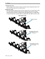
Page 129: ...ea in the label design Move the Print Reading Sensor The location of the cut is determined by the Print Reading Sensor The simplest way to get the cut in the correct location on the film is to move the Print Reading Sensor up or down the length of the Mandrel Fin until the cut area is centered inside the Sensor a Holding the Print Reading Sensor Mount loosen the Wing Nuts that hold it in place as ...

Page 130: ...r in its new position d Close the Front Door of the LX 150 and run a few test cuts by pressing the 1 Cycle Button on the Manual Screen of the HMI e If the cut is perfectly centered in the cut area no further setup is needed Moving the Print Reading Sensor AFM 4510001 00215 01 Print Reading Sensor Print Reading Sensor Mount Wing Nuts Cut Mark Precisely in Center of Cut Area Cut Mark ...

Page 131: ...e to determine the distance in mm between the location of the actual cut and the center of the cut area This is the Print Reg Dwell value b On the HMI select the Setting Tab to go to the Setting Screen c Enter the Print Reg Dwell value in the Print Reg Dwell Field and press the Set Button d Run a few more test cuts The cut should now appear in the center of the cut area If not repeat the Fine Tune...

Page 132: ...132 Setup 4510001 REV B 220620 ...

Page 133: ...0 60 Hz AC power source Turn the Main Power Switch on the back of the Electronics Cabinet to the On position On the HMI turn the Power Switch clockwise to the On position A buzzer may sound to indicate that the system has been turned on A Startup Screen will briefly display The Notice Cutter Needs Positioning Screen will display Follow the steps to get the Cutter Blades in their home position see ...

Page 134: ...top Screen will display when the E Stop has been pressed ATTENTION Do not use the E Stop Button for routine pauses or halts to production as this can damage the system over time Instead press the Stop Button To Address the Fault and Resume Labeling Press the Buzzer Stop Button Determine why the Emergency Stop Button was pressed If a safety hazard exists thoroughly address and eliminated the safety...

Page 135: ... information read the Software section starting on page 77 Items Needed to Load and Test a Recipe Ruler To Load and Test a Recipe Power on the LX 150 see Powering the System On on page 133 Position the Cutter Blades see Positioning the Cutter Blades on page 117 Ensure that the desired film is properly loaded on the UR 1 and threaded through the system If it is not load and thread a roll of the des...

Page 136: ...Conveyor c Turn the Timing Screw Assembly on by pressing the button below Timing Screw The Timing Screw Assembly will not move yet d With bottles lined up behind the Timing Screw Assembly on the Conveyor press the Start Button on the HMI Test one bottle at a time e Watch the bottles for accuracy in label placement If labels are not going onto the bottles the position of the Work Detective Sensor s...

Page 137: ...ctive Sensor Position Correctly Timed Labels Work Detective Sensor is correctly positioned Labels Being Applied Too Late Work Detective Sensor should be moved upstream Labels Being Applied Too Soon Work Detective Sensor should be moved downstream ...

Page 138: ...ndrel too late decrease the value blue buttons on left to move the Work Detective Sensor further upstream o If labels are being shot off the Mandrel too soon increase the value red buttons on right to move the Work Detective Sensor further downstream c Repeat the previous step testing to see where the LX 150 places the labels d If needed continue adjusting Print Reg Dwell until labels go onto all ...

Page 139: ... Ready all of the appropriate peripherals as described below NOTE None of the peripherals will actually start until the Start Button on the HMI has been pressed a Press the Screw Button to ready the Timing Screw Assembly b Press the Brush Button to ready the Brushdown Assembly c Press the Aux Belt Button to ready the Auxiliary Belts Bottle Holding Devices if used d Similarly ready any other periph...

Page 140: ...beled If a pause in production is needed for example labels are shooting onto the Conveyor Belt instead of onto the bottles press the Stop Button on the HMI and address the issue before restarting ATTENTION Do not use the E Stop Button for routine pauses or halts to production as this can damage the system over time Instead press the Stop Button HMI Start Button Stop Button ...

Page 141: ... Spool of label film Scissors Splicing Tape Hole Punch To Switch Film Rolls When the film roll is almost empty push the Stop Button on the HMI to stop the LX 150 Looking at the film as it lays on the Splicing Table find the halfway point in the label design and measure an additional 10 15mm further down on it Cut the old film across that point in the label design If a new roll is not already on th...

Page 142: ...and cut the old film across that point Open the cut in the new film to form a pocket and squeeze in slightly on the end of the old film so that it can fit into that pocket New Film Roll Beginning of New Film Roll End of Old Film Roll Running New Film Down Onto Splicing Table Splicing Table Halfway Through Label Design Cutting the Beginning of the New Film 10 15mm Halfway Through Label Design Begin...

Page 143: ...ver the location where the end of the new film meets the old film to secure both pieces of film together The tape should cover both sides top and bottom of the flat film Sliding the Old Film into the New Film Beginning of New Film End of Old Film Pocket Label Designs Align in Overlap Area Applying Splicing Tape and Cutting Air Holes Beginning of New Film End of Old Film Splicing Tape Punched Holes...

Page 144: ...clockwise ATTENTION Failure to correctly set the rotation direction of the film will result in the film winding back onto the Film Spool potentially damaging the film and undoing the work of threading the film through the system Press the Start Button on the HMI to restart the LX 150 and resume labeling Watch the first few bottles labeled and remove the one with the splicing tape from the Conveyor...

Page 145: ...TION Do not use the E Stop Button for routine pauses or halts to production as this can damage the system over time Instead press the Stop Button On the HMI turn the Power Switch counterclockwise to the Off position On the back of the Electronics Cabinet turn the Main Power Switch counterclockwise to the Off position HMI Power Switch Stop Button AFM 4510001 00053 01 Main Power Switch ...

Page 146: ...146 Operation 4510001 REV B 220620 ...

Page 147: ...entative maintenance schedule below can help ensure optimal performance minimize downtime and help with budgeting for required replacement parts that should be ordered in advance ATTENTION Some maintenance activities below should be performed by an in house mechanical professional or trained AFM Service Technician If in doubt please contact your authorized AFM Distributor Frequency Procedure Page ...

Page 148: ...rings inside the Mandrel 157 Replace the Film Drive Bearings inside the Mandrel 157 Replace the Applicator Bearings inside the Mandrel 157 Replace the Support Wheels Part Number 4500183 177 Replace the Film Drive Wheels Part Number 4500704 176 Replace the Applicator Wheels Part Number 4500128 178 Replace the Cutter Bearings 169 Every 2 3 Years Replace the Film Feed Drive Belt Call Distributor Repl...

Page 149: ...off the LX 150 see Powering the System Off on page 145 and unplug it from the power source WARNING Failure to power off the system and unplug it from its power source before cleaning can result in severe electric shock or death Cleaning the Outside of the LX 150 and UR 1 Spray the cleaner onto the Cloth Paper Towels Wipe the outside of the LX 150 and UR 1 thoroughly being careful not to get any in...

Page 150: ...east once a week remove the Mandrel see Removing the Mandrel on page 152 and use a light Brush to gently clean lens of the Print Reading Sensor ATTENTION Do not use Compressed Air Doing so can damage the lens and void the warranty Print Reading Sensor AFM 4510001 00109 01 Lens ...

Page 151: ...ctive Sensor At least once a week use a Non abrasive Lint free Wipe Part Number 2005470 to gently clean the Eye of the Work Detective Sensor and Reflector AFM 4510001 00121 01 Work Detective Sensor and Reflector Work Detective Sensor Applicator Wheels Reflector ...

Page 152: ...osition away from the Mandrel ATTENTION As the various Wheels are loosened there will be nothing left supporting the Mandrel To ensure that the Mandrel does not fall use one hand to hold it in place while loosening the Wheels WARNING Wear Cut Resistant Gloves and do not hold the Mandrel near the Cutter Assembly Cutter Blades are very sharp and can easily cause severe cuts a Unlock the Applicator W...

Page 153: ...l gently lift the Mandrel straight upward and out of the LX 150 being careful not to knock the Print Reading Sensor Wheels That Contact the Mandrel Film Drive Wheels Applicator Wheels Support Wheels AFM 4510001 00232 01 AFM 4510001 00156 01 Removing the Mandrel AFM 4510001 00156 01 Mandrel ...

Page 154: ...ch Cut Resistant Work Gloves Compressed Air To Clean the Cutter Notch Remove the Mandrel see Removing the Mandrel on page 152 Examine the Cutter Notch for any debris If needed spray Compressed Air into the Cutter Notch until all debris has been removed To resume labeling reinstall the Mandrel see Installing the Mandrel on page 56 and close the Front Door of the LX 150 Cleaning the Cutter Notch Cut...

Page 155: ...in freely are free of dust and contaminants and clean as necessary using compressed air If they still do not spin freely replace them see Replacing the Bearings in the Mandrel on page 157 With the Mandrel still removed manually spin the Support Wheels Film Drive Wheels and Applicator Wheels inside the LX 150 to make sure that they also spin freely and use compressed air to clean them as needed If ...

Page 156: ...c residue on the Wheels This can cause the film to slip as it is being fed leading to loss of registration Check for any shiny buildup on the Applicator Wheels and Film Drive Wheels If any residue is present the Applicator Wheels and Film Drive Wheels can be cleaned using distilled or de ionized or reverse osmosis filtered water ATTENTION Do not use alcohol on the rubber wheels Doing so can damage...

Page 157: ...r New Support Bearings 4 sets New Film Drive Bearings 4 sets New Applicator Bearings 2 sets To Replace the Mandrel s Bearings Remove the Mandrel see Removing the Mandrel on page 152 Use the Screwdriver to push out the Axles for all Bearings in the Mandrel making note of which Axle goes with which location on the Mandrel The Axles are only held in place by tension friction Replacing All Bearings an...

Page 158: ...on the Film Drive Axle c Push the Film Drive port Axle the rest of the way into its original position d Repeat for all Film Drive Axles and Film Drive Bearings e Confirm that all Film Drive Bearings spin freely Install the new Applicator Bearings a Slide a Applicator Axle partly back into its hole b Line up the new Applicator Bearings on the Applicator Axle c Push the Applicator Axle the rest of t...

Page 159: ...checked for signs of wear This can be done simply by viewing the length of it turning the Film Drive Wheels by hand to expose parts of the Belt that are not readily visible If any wear is observed on the Belt it should be replaced by AFM Support Areas to Observe Film Feed Drive Belt Film Feed Drive Belt AFM 4510001 00150 01 ...

Page 160: ... using the camera app on your mobile device Time 0 00 0 50 Items Needed to Remove the Cutter Assembly Allen Wrench included in Tool Kit Cut Resistant Work Gloves To Remove the Cutter Assembly Open the Front Door of the LX 150 Remove the Mandrel see Removing the Mandrel on page 152 Take the Cutter Drive Belt off the Cutter Drive Pulley a Turn the Tensioner Lock counterclockwise to unlock it and pus...

Page 161: ...he 4 Screws holding it to the Cutter Support Arms c Store the Cutter Guard with its Cutter Assembly d Set aside the Screws to attach the new Cutter Guard to the Cutter Support Arms ATTENTION When the Screws have been removed there will be nothing left holding the Cutter Guard in place To ensure that the Cutter Guard does not fall use hands to gently hold it in place while loosening the Screws Pull...

Page 162: ... link https www youtube com watch v 036vSOgbL0A Or scan the QR code at right using the camera app on your mobile device Time 0 50 2 52 Items Needed to Replace the Cutter Blades Allen Wrench included in Tool Kit Cut Resistant Work Gloves New Cutter Blades Part Number 4501151 To Replace the Cutter Blades Remove the Mandrel see Removing the Mandrel on page 152 Remove the Cutter Assembly see Removing ...

Page 163: ...ade in position Slide a new Blade in so that its non sharp edge rests against that ridge The sharp edge of the blade should be facing counterclockwise b Retighten the Screws to hold the new Cutter Blade securely in position c Repeat this for all of the Cutter Blades ensuring that an equal length of each Cutter Blade is extending from each Cutter Blade Housing When finished o The Cutter Blades shou...

Page 164: ...Cutter Drive Belt see Checking the Cutter Drive Belt on page 165 d If there is wear on either Belt or if they are due for replacement according to the Preventative Maintenance Schedule see page 147 replace the Belts see Replacing the Timing Belt and Cutter Drive Belt on page 167 e Use the Cutter Drive pulley to manually return the Cutter Blades to the home position with the Cutter Home Tab pointin...

Page 165: ...utter Assembly properly installed check the condition of the Cutter Drive Belt Order a replacement at the first sign of wear WARNING Failure to replace a worn Timing Belt can impair system performance can damage the equipment and can result in injury Verify proper tension on the Cutter Drive Belt and adjust if needed by unlocking the Tensioner and tightening it see Tensioner Unlocking Adjusting Lo...

Page 166: ...the Timing Belt by verifying that rotating the Cutter Drive Pulley turns all Cutter Blades in unison and by tugging gently outward on it Adjust the Timing Belt if needed by moving the position of the Tension Adjustment Wheel The tension on the Timing Belt should always be tight enough to ensure consistently precise rotation of the Cutter Blades Reinstall the Cutter Assembly see Installing the Cutt...

Page 167: ...edium Part Number 4501707 o Large Part Number 4501697 To Replace the Timing Belt and Cutter Drive Belt 1 Power off the LX 150 see Powering the System Off on page 145 and unplug it from the power source 2 Remove the Mandrel see Removing the Mandrel on page 152 3 Remove the Cutter Assembly see Removing the Cutter Assembly on page 160 4 On the underside of the Cutter Assembly carefully remove each of...

Page 168: ... Timing Belt on page 166 8 Install new Cutter Blades see Replacing the Cutter Blades on page 162 9 Reinstall the Cutter Assembly see Installing the Cutter Assembly on page 53 looping the new Cutter Drive Belt over the Cutter Drive Pulley Timing Belt Cutter Drive Pulley AFM 4510001 00207 01 Tension Adjustment Wheel Cutter Blade Housing Timing Pulley AFM 4510001 00116 01 Tensioner Lock Cutter Drive ...

Page 169: ...tant Work Gloves New Cutter Bearings Part Number 4500173 New Cutter Blades Part Number 4501161 To Replace the Cutter Bearings 1 Power off the LX 150 see Powering the System Off on page 145 and unplug it from the power source 2 Remove the Mandrel see Removing the Mandrel on page 152 3 Remove the Cutter Assembly see Removing the Cutter Assembly on page 160 4 On the underside of the Cutter Assembly c...

Page 170: ...ad it from around the Cutter Blade Housings Wheels and Pulleys in the Cutter Assembly 6 Lift each old Cutter Housing and Timing Pulley off its Shaft disassembling them Timing Belt Cutter Drive Pulley AFM 4510001 00207 01 Tension Adjustment Wheel Cutter Blade Housing Timing Pulley Cutter Blade Housing Timing Pulley Cutter Bearings Underside of Cutter Assembly Cutter Blade Cap of Cutter Blade Housin...

Page 171: ...e new ones 8 Reassemble the components of each Cutter Housing and Timing Pulley on their Shafts as shown in the diagram above 9 Install the new Cutter Blades see Replacing the Cutter Blades on page 162 10 Reinstall the Cutter Assembly see Installing the Cutter Assembly on page 53 ...

Page 172: ...st Once a year the Shafts of the Head Height Adjust should be lightly greased to ensure smooth performance Shafts of the Head Height Adjust Shafts of Head Height Adjust AFM 4510001 00242 01 AFM 4510001 00229 01 2 of 3 Shafts of Head Height Adjust 2 of 3 Shafts of Head Height Adjust ...

Page 173: ... Adjust Once a year the Shafts of the Applicator Wheel Vertical Adjust should be lightly greased to ensure smooth performance AFM 4510001 00098 01 Shafts of the Applicator Wheel Vertical Adjust 3 Shafts of the Applicator Wheel Vertical Adjust 3 Shafts of the Applicator Wheel Vertical Adjust ...

Page 174: ... Adjusts Once a year the Shafts of the Film Drive Wheel Adjusts should be lightly greased to ensure smooth performance AFM 4510001 00304 01 Shafts of the Film Drive Wheel Adjusts 5 Shafts of the Film Drive Wheel Adjusts AFM 4510001 00111 01 5 Shafts of the Film Drive Wheel Adjusts ...

Page 175: ...year the Shafts of the Film Drive Wheel Adjusts and Support Wheel Adjusts should be lightly greased to ensure smooth performance Shafts of the Support Wheel Adjusts 3 Shafts of the Upper Support Wheel Adjusts AFM 4510001 00110 01 AFM 4510001 00111 01 3 Shafts of the Lower Support Wheel Adjusts ...

Page 176: ...145 and unplug it from the power source 2 Remove the Mandrel see Removing the Mandrel on page 152 3 Remove the Film Drive Wheels Each Film Drive Wheel has two Set Screws at 90 to each other holding it in place The Set Screws are located on the Shaft just behind the Film Drive Wheel They may be on the top bottom or side depending on the rotation of the Wheel at the time a Use the Allen Wrench to lo...

Page 177: ...on page 152 3 Remove the Support Wheels Each Support Wheel has a Machine Screw and a Bushing holding it in place The Machine Screw is in the center of the Support Wheel a Use the Allen Wrench to remove the Machine Screw b Pop off the old Support Wheel The Bushing will come off as well the flange of the Bushing is visible just behind the Machine Screw c Replace the old Support Wheel with a new Supp...

Page 178: ...m the power source 2 Remove the Mandrel see Removing the Mandrel on page 152 4 Each Applicator Wheel has two Set Screws at 90 to each other holding it in place The Set Screws are located on the Shaft just behind the Applicator Wheel They may be on the top bottom or side depending on the rotation of the Wheel at the time a Use the Allen Wrench to loosen the Set Screws b Pop off the old Applicator W...

Page 179: ...128 Verify that the Print Reading Sensor Eye is looking through the slot in the Mandrel Fin Verify that the correct recipe is loaded Check that the Film Drive Wheels are tight against the Film Drive Bearings causing the Wheels to slip on the label and thus preventing them from advancing the film with precision If needed adjust the position of the Film Drive Wheels see Film Drive Wheels Unlocking A...

Page 180: ... Reading Sensor If the yellow light turns on quickly press the Button as many times as needed until the light turns off Once the light is off or if it was already off quickly press the Button until the yellow light turns on and stays on Pull the label film down slightly until the printed area of the label film is in the beam of the Print Reading Sensor The yellow light should turn off The Sensor s...

Page 181: ...hould open and maintain the Electronics Cabinet ATTENTION The Electronics Cabinet and the components within it should never be sprayed with water cleaner or other liquids Doing so can damage the equipment and will void the warranty Items Needed to Clean the Electronics Cabinet Rubber Soled Shoes Key to the Electronics Cabinet Compressed Air To Clean the Electronics Cabinet Ensure that the system i...

Page 182: ...the Door of the Electronics Cabinet Use Compressed Air to spray away any dust or other contaminants With one hand only close the Door of the Electronics Cabinet With one hand only use the Square Key to latch the upper and lower Door Latches of the Electronics Cabinet ...

Page 183: ... Timing Screw Assembly speed and Conveyor speed The Work Detective Sensor is too far upstream or downstream Move the Work Detective Sensor see the Band Release Delay portion of Loading a Recipe on page 135 The Mandrel is too far up from the tops of the bottles or too close to them Adjust the height of the Head Assembly see Fine Tuning the LX 150 Position on page 60 Labels are bouncing back up off ...

Page 184: ... on page 135 The Film Drive Wheels are not tight enough against the Film Drive Bearings slipping and preventing them from advancing the film with precision Adjust the Film Drive Wheels see Film Drive Wheels Unlocking Adjusting Locking on page 112 The Print Reading Sensor Lens is dirty or dusty Clean the Print Reading Sensor Lens see Cleaning the Print Reading Sensor on page 150 The Cut Length or s...

Page 185: ...Electrical Schematics 185 4510001 REV B 220620 Electrical Schematics LX150N J001 220V Main Power 24 VDC Power Supply and Applicating Motor Circuit ...

Page 186: ...186 Electrical Schematics 4510001 REV B 220620 LX150N J002 220V Indicator Lamp Circuit ...

Page 187: ...Electrical Schematics 187 4510001 REV B 220620 LX150N J003 220V PLC ...

Page 188: ...LICATION FAIL DET WLL1702N132 XB START BUTTON 1a XC STOP BUTTON 1b XD SAFETY FUNCTION FOR DOOR RY0 NO XE XF TIMING SCREW SENSOR SPARE WL9G3N1132PO6 OUTPUT REMARK Y0 TO CUTTER DRIVE PULSE Y1 TO CUTTER DRIVER SIGN Y2 TO INFEED DRIVER PULSE Y3 TO INFEED DRIVER SIGN Y4 WORKING RY1 APPLICATING MOTOR Y5 BUZZER RY2 Y6 PRINT FUNCTION USE Y7 BRUSH MOTOR RY3 Y8 TOWER LIGHT YELLOW RY4 Y9 FILM ROLL MOTOR RY5 ...

Page 189: ...Electrical Schematics 189 4510001 REV B 220620 LX150N J005 220V ...

Page 190: ...190 Electrical Schematics 4510001 REV B 220620 LX150N J006 220V ...

Page 191: ...Electrical Schematics 191 4510001 REV B 220620 LX150N J007 220V HMI ...

Page 192: ...192 Electrical Schematics 4510001 REV B 220620 LX150N J008 220V UR1 Unwind Circuit ...

Page 193: ...Electrical Schematics 193 4510001 REV B 220620 LX150N J009 220V UR1 Unwind Cable ...

Page 194: ...194 Electrical Schematics 4510001 REV B 220620 LX150N J010 220V Film Roll Motor ...

Page 195: ...Electrical Schematics 195 4510001 REV B 220620 LX150N J011 220V Timing Screw Motor Drive ...

Page 196: ...196 Electrical Schematics 4510001 REV B 220620 LX150N J012 220V Timing Screw Motor ...

Page 197: ...Electrical Schematics 197 4510001 REV B 220620 LX150N J013 220V Brushdown Circuit ...

Page 198: ...198 Electrical Schematics 4510001 REV B 220620 LX150N J014 220V Auxiliary Belt Bottle Holding Device Drive ...

Page 199: ...Electrical Schematics 199 4510001 REV B 220620 LX150N J015 220V Auxiliary Belt Bottle Holding Device Motors ...

Page 200: ...200 Electrical Schematics 4510001 REV B 220620 LX150N J016 220V PLC I O Extension ...

Page 201: ...Electrical Schematics 201 4510001 REV B 220620 LX150N J001 480V Main Power 24 VDC Power Supply and Applicating Motor Circuit ...

Page 202: ...202 Electrical Schematics 4510001 REV B 220620 LX150N J002 480V Indicator Lamp Circuit ...

Page 203: ...Electrical Schematics 203 4510001 REV B 220620 LX150N J003 480V PLC ...

Page 204: ...LICATION FAIL DET WLL1702N132 XB START BUTTON 1a XC STOP BUTTON 1b XD SAFETY FUNCTION FOR DOOR RY0 NO XE XF TIMING SCREW SENSOR SPARE WL9G3N1132PO6 OUTPUT REMARK Y0 TO CUTTER DRIVE PULSE Y1 TO CUTTER DRIVER SIGN Y2 TO INFEED DRIVER PULSE Y3 TO INFEED DRIVER SIGN Y4 WORKING RY1 APPLICATING MOTOR Y5 BUZZER RY2 Y6 PRINT FUNCTION USE Y7 BRUSH MOTOR RY3 Y8 TOWER LIGHT YELLOW RY4 Y9 FILM ROLL MOTOR RY5 ...

Page 205: ...Electrical Schematics 205 4510001 REV B 220620 LX150N J005 480V ...

Page 206: ...206 Electrical Schematics 4510001 REV B 220620 LX150N J006 480V ...

Page 207: ...Electrical Schematics 207 4510001 REV B 220620 LX150N J007 480V HMI ...

Page 208: ...208 Electrical Schematics 4510001 REV B 220620 LX150N J008 480V UR1 Unwind Circuit ...

Page 209: ...Electrical Schematics 209 4510001 REV B 220620 LX150N J009 480V UR1 Unwind Cable ...

Page 210: ...210 Electrical Schematics 4510001 REV B 220620 LX150N J010 480V Film Roll Motor ...

Page 211: ...Electrical Schematics 211 4510001 REV B 220620 LX150N J011 480V Timing Screw Motor Drive ...

Page 212: ...212 Electrical Schematics 4510001 REV B 220620 LX150N J012 480V Timing Screw Motor ...

Page 213: ...Electrical Schematics 213 4510001 REV B 220620 LX150N J013 480V Brushdown Circuit ...

Page 214: ...214 Electrical Schematics 4510001 REV B 220620 LX150N J014 480V Auxiliary Belt Bottle Holding Device Drive ...

Page 215: ...Electrical Schematics 215 4510001 REV B 220620 LX150N J015 480V Auxiliary Belt Bottle Holding Device Motors ...

Page 216: ...216 Electrical Schematics 4510001 REV B 220620 LX150N J016 480V PLC I O Extension ...

Page 217: ...Specification Quantity 1 4500171 Bearing 5BE016900ZZJ 4 2 4502132 Seat Bearing 5BE03UCFL20630 4 3 4502935 Motor 5CH65U5IK60ST 15RH 2 4 4502786 Handle 5BC024030X78M10SR 2 5 4503700 Torque Arm 5CH65FA40001 2 6 4503330 Tripod 5BD31M20X180S 4 7 4503701 Electric Box 5AC6100851 1 8 4503702 Knob 30 5AB61AC222PNA2B 2 ...

Page 218: ...at LE100 GM02 2 G3 4502574 Slide Seat LE100 GM03 2 G4 4502785 Screw LE100TX1 GM05 2 G5 4503703 Roller LG150 GM02 2 G6 4503704 Axis LG150 GM03 2 G7 4502604 Ring LG150 GM04 4 G8 4502776 Plate LG150 GC02 4 G9 4503705 Mat Seat LG150 GM11 2 G10 4502778 Plate LG150 GM14 4 G11 4503706 Shelf LG150 GP01 1 G12 4503707 Plate LG150 GP02 1 G13 4503708 Fixed LG150 GP05 1 ...

Page 219: ...Diagrams and Parts Lists 219 4510001 REV B 220620 Dancer Assembly ...

Page 220: ...DA 1 5 4503709 Straight Cable M12 F5N 200 2M 5AB94M12F5N200 1 Item Part Number Description Specification Quantity K1 4502898 Bearing Set LG150K2 KM01 5HGLG150K2KM01 6 K2 4503710 Fixed Seat LG150K2 KM02 5HGLG150K2KM02 2 K3 4502899 Guide Rod LG150K2 KM03 5HGLG150K2KM03 6 K4 4502900 Axis LG150K2 KM04 5HGLG150K2KM05 4 K5 4502901 Axis LG150K2 KM05 5HGLG150K2KM05 3 K6 4502902 Roller LG150K2 KM06 5HGLG15...

Page 221: ...Diagrams and Parts Lists 221 4510001 REV B 220620 Cutter Assembly ...

Page 222: ...umber Description Specification Quantity E1 4501728 TIMING PULLEYS LG150T EC01 5 E2 4503003 TIMING PULLEYS LG150T EC02X2 2 E3 4501741 PULLEYS LG150T EC03 1 E4 4503713 PLATES LG150T EM01 1 E5 4503319 SET COLLARS LG150T EM02 5 E6 4500224 HOUSING LG150T EM03 5 E7 4503271 SET COLLARS LG150T EM04 5 E8 4503263 AXLS LG150T EM05 5 E9 4503261 PULLEYS LG150T EM06 6 E10 4503262 SET COLLARS LG150T EM07 6 E11 ...

Page 223: ...t Item Part Number Description Specification Quantity 01 4501158 HAND WHEEL KRN80 D 10 M6 2 HOLE 5BC01KRN80 1 02 4502388 MOVABLE HANDLE CB50M6 5BC01CB50M6 1 03 4501792 HANDLE TRT40 M6X20 SILVER 5BC02TRT40M6X20 1 04 4501716 TIMING BELT W 3 8 XL L 136 5BB023X136XL 2 Drawing LG150T F01 ...

Page 224: ...0TFM02 1 F03 4503718 PLATES LG150T FM03 5HGLG150TFM03 1 F04 4503719 SCREWS LG150T FM04 5HGLG150TFM04 1 F05 4503720 SHAFTS LG150T FM05 5HGLG150TFM05 2 F06 4503721 PLATES LG150T FM08 5HGLG150TFM08 1 F07 4503722 PAD LG150T FM21 5HGLG150TFM21X1 1 F08 4503723 PAD LG150T FM22 5HGLG150TFM22X1 1 F09 4503580 GUIDE LG150T FM02X1 5HGLG150TFM02X1 2 F10 4503724 PLATES LG150T FM02X2 5HGLG150TFM02X2 2 ...

Page 225: ...Diagrams and Parts Lists 225 4510001 REV B 220620 Applicator Assembly ...

Page 226: ...10 4503361 AXIS LG150T FM23 5HGLG150TFM23 2 F11 4503362 AXIS LG150T FM24 5HGLG150TFM24 2 F12 4502675 AXIS LG150T FM25 5HGLG150TFM25 1 F13 4502675 1 AXIS LG150T FM26 5HGLG150TFM26 1 F14 4503086 SHAFTS LG150T FM27 5HGLG150TFM27 1 F15 4503085 SHAFTS LG150T FM28 5HGLG150TFM28 1 F16 4503359 PLATES LG150T FM29 5HGLG150TFM29 2 F17 4502712 PLATES LG150T FM30 5HGLG150TFM30 2 F18 4503051 FIXED BLOCK LG150T ...

Page 227: ...Diagrams and Parts Lists 227 4510001 REV B 220620 LX 150 Frame ...

Page 228: ...ption Specification Quantity 1 4503330 ADJUSTER PADS M20X150L DS9020150 5BD31M20X180S 4 2 4505240 CASTER 3 X1 5BD01075X25 4 Item Part Number Description Specification Quantity A1 4503730 MAIN BODY LG150T AP01 1 A2 4503731 PLATES LG150T AP02 4 A3 4503732 PLATES LG150T AP03 2 ...

Page 229: ...Diagrams and Parts Lists 229 4510001 REV B 220620 Head Height Adjust ...

Page 230: ...ification Quantity B1 4503733 BEVEL GEAR LG150T BC01 2 B2 4503734 TIMING PULLEYS LG150T BC02 1 B3 4503735 TIMING PULLEYS LG150T BC05 1 B4 4503736 PLATES LG150T BM01 1 B5 4503737 CLAMPS LG150T BM02 1 B6 4503738 CLAMPS LG150T BM03 1 B7 4503739 PLATES LG150T BM04 1 B8 4503740 PLATES LG150T BM05 1 B9 4503741 CLAMPS LG150T BM06 2 B10 4503742 SCREWS LG150T BM07 1 B11 4503743 SHAFTS LG150T BM08 4 B12 450...

Page 231: ...ATES LG150T UP02 1 B31 4503762 SCREWS LG150T UP03 1 B32 4503763 PLATES LG150T BM13 2 B33 4503764 SHAFTS LG150T BM17 1 B34 4503765 PLATES LG150T BM18 1 B35 4503766 PLATES LG150T BM19 1 B36 4503767 PLATES LG150T BM20 1 B37 4503768 PLATES LG150 BP14 1 B38 4503769 PLATES LG150 UP04 1 B39 4503770 PLATES LG150 UP05 1 B40 4503004 PULLEY LG150 WC04 1 B41 4503771 SENSOR HOLDER LG150T AP04 1 ...

Page 232: ...C4514104 3 3 4501419 SAFETY SWITCH QKS 8 AC400V2A 5AB17QKS8 1 Item Part Number Description Specification Quantity B1 4503772 PANELS LG150T BP03 1 B2 4503773 PANELS LG150T BP07 2 B3 4503774 PANELS LG150T BP08 1 B4 4503775 PANELS LG150T BP09 1 B5 4503776 PLATES LG150T BP11 3 B6 4503777 PLATES LG150T BP13 1 B7 4503778 DOOR LG150T BC03X1 1 B8 4503779 HEAD FRAME LG150T BP16 1 ...

Page 233: ... BEARINGS 6900ZZJ 5BE016900ZZJ 2 2 4502939 TOWER LIGHT TPTL5 74 4 24V 5AE05TRT244ROGW 1 3 4503780 HOLDER TPTL6 F 5AE05TPTL6F 1 Item Part Number Description Specification Quantity B1 4503781 PLATES LG150T BP04 1 B2 4503782 PLATES LG150T BP15 2 B3 4503783 ROLLER LG150T BM10 1 B4 4503784 AXIS LG150T BM11 1 B5 4503785 SET COLLARS LG150T WM35 2 ...

Page 234: ... Item Part Number Description Specification Quantity 1 4501461 SENSOR WF5 40B410 5AB04WF540B410 1 Item Part Number Description Specification Quantity U1 4503786 PLATES LG150T UM12 1 U2 4502435 PLATES LG150T UM13 1 U3 4502436 PLATES LG150T UM14 1 U4 4503787 PLATES LG150T UM15 1 ...

Page 235: ...Diagrams and Parts Lists 235 4510001 REV B 220620 Support and Film Drive Wheel Assemblies ...

Page 236: ...G150T WC01 2 W2 4500705 TIMING PULLEYS LG150T WC02 2 W3 4503019 TIMING PULLEYS LG150T WC03 1 W4 4500704 TIMING PULLEYS D50X20X35XD16 5HFQLB100WM13X1 4 W5 4503790 PLATES LG150T WM01 1 W6 4503791 PLATES LG150T WM02 1 W7 4503792 CLAMPS LG150T WM03 1 W8 4503793 PLATES LG150T WM04 1 W9 4503794 AXIS LG150T WM05 4 W10 4503795 SCREWS LG150T WM06 1 W11 4503796 SCREWS LG150T WM07 1 W12 4503797 COUPLINGS LG1...

Page 237: ...AXIS LG150T WM25 4 W30 4503815 PLATES LG150T WM26 2 W31 4503816 PLATES LG150T WM27 2 W32 4503817 SCREWS LG150T WM28 2 W33 4503818 SCREWS LG150T WM29 2 W34 4503819 CLAMPS LG150T WM30 2 W35 4503820 PLATES LG150T WM32 1 W36 4503821 PLATES LG150T WM33 1 W37 4503822 PLATES LG150T WM34 1 W38 4503823 PLATES LG150T BP10 1 ...

Page 238: ...238 Diagrams and Parts Lists 4510001 REV B 220620 400mm Timing Screw Assembly ...

Page 239: ...duct Specific 1 A2 4503857 Board 5HGLB100L2LM01 LB100L2 LM01 2 A3 4503858 Board 5HGLB100L2LM02 LB100L2 LM02 2 A4 4503846 Board 5HGLB100L2LM03 LB100L2 LM03 1 A5 4503847 Place 5HGLB100L2LM04 LB100L2 LM04 1 A6 4503848 Place 5HGLB100L2LM05 LB100L2 LM05 2 A7 4503849 Place 5HGLB100L2LM06 LB100L2 LM06 1 A8 4503850 Board 5HGLB100L2LM07 LB100L2 LM07 1 A9 4503851 Board 5HGLB100L2LM08 LB100L2 LM08 1 A10 4503...

Page 240: ...240 Diagrams and Parts Lists 4510001 REV B 220620 ...

Page 241: ... Setup TRT 2 52 https youtu be shn5o7MZXbM Machine Adjustments and Fine Tuning TRT 1 42 https youtu be Q3k865kFjmw Film Setup TRT 2 52 https youtu be bLK238uuRn0 Installing the Mandrel TRT 1 07 https youtu be _I6lIKRz6qQ Cutter Adjustments TRT 2 52 https youtu be 036vSOgbL0A Applicator Wheel Adjustment TRT 1 18 https youtu be ZNER7s69QEA Timing Screw Setup and Adjustments TRT 5 26 https youtu be w...

Page 242: ...510001 REV B 220620 Capabilities Multi Pack Sleeving TRT 1 19 https youtu be wCvL Gp2wTo Full Body Juice Label Application TRT 1 05 https youtu be EJcKVPJ 5Fc Candle Sleeve Application TRT 1 00 https youtu be ZDe4MC4_g2c ...

Page 243: ...f the original warranty Repairs All in house repairs are rigorously tested for optimum operation and performance and warranted to be under normal and proper use free from defects in material and workmanship for a period of 90 days from the date of service Shrinking Quality Shrinking quality achieved in a given application is dependent on the film product installation material handling and the main...

Page 244: ... PRODUCT REPAIRED OR ALTERED BY PERSONS OTHER THAN AUTHORIZED AFM REPRESENTATIVES WILL NOT BE COVERED BY THIS WARRANTY THIS WARRANTY DOES NOT APPLY TO CONSUMABLE ITEMS EXCEPT AS EXPRESSLY PROVIDED IN THIS WARRANTY AFM MAKES NO REPRESENTATION OR WARRANTY EXPRESSED OR IMPLIED WITH RESPECT TO THE PRODUCT INCLUDING WITHOUT LIMITATION ANY WARRANTY AS TO MERCHANTABILITY FITNESS FOR A PARTICULAR PURPOSE ...

Page 245: ...ng operating or maintaining the LX 150 contact your authorized AFM reseller or AFM Technical Support Phone 714 974 9006 Fax 763 795 8867 Email info afmsleeves com Web www afmsleeves com Thanks again for your purchase of AFM products We are pleased to be a part of your shrink sleeving needs ...

Page 246: ...246 Technical Support 4510001 REV B 220620 ...
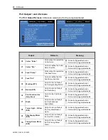
Reviews: