background image

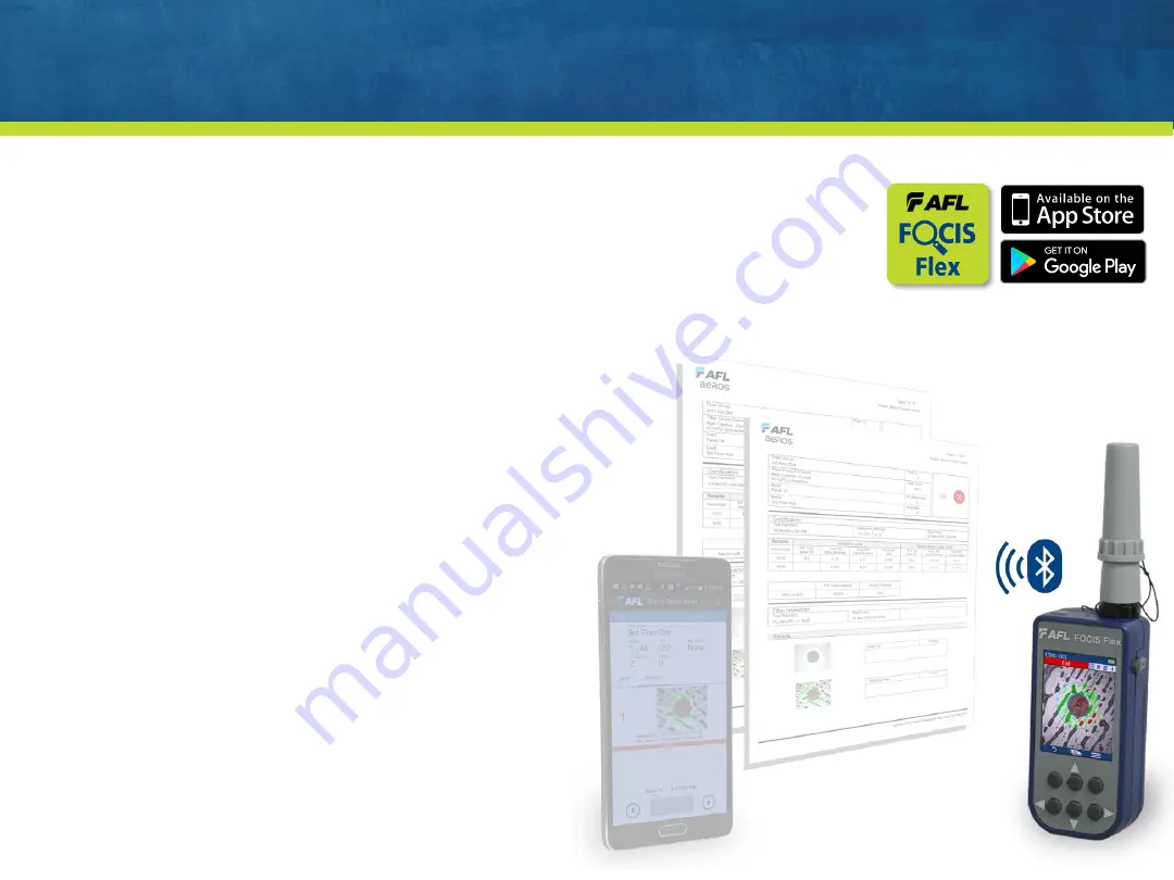
Using FOCIS Flex with FOCIS Flex App

Download FOCIS Flex App to your Mobile Device

Pair FOCIS Flex to your mobile device

In mobile device Bluetooth Settings, make device visible

In FOCIS Flex Bluetooth Settings, select ‘Pair to new device’

Select displayed mobile device (when device is displayed and hourglass disappears)

Select ‘Set as Default’

Verify FOCIS Flex indicates it is paired with your Mobile Device

In Capture Settings, configure FOCIS Flex to send on 1

st

or 2

nd

Capture Key

From Live Image mode, view connector end-face and press Capture

FOCIS Flex will capture image and send it to your mobile device

FOCIS Flex App will display received image

For App details, see FOCIS Flex Inspection | aeRos User’s Guide

AFL Confidential

38

Summary of Contents for FOCIS Flex

Page 1: ...AFL Confidential FOCIS Flex Intro to Operation May 2017 1...

Page 2: ...tery Operation Image Display Modes Live Display Mode Manual Focus One time Auto focus Auto focus Capture Captured Image Display Mode Main Menu Settings Mode Pass Fail Analysis Settings Auto focus Enab...

Page 3: ...Image pairing e g save image before after cleaning International languages Instant On power up Inspection Reporting Supported in TRM 2 0 Included in both Basic and Advanced versions Free download fro...

Page 4: ...avigation Edit keys Display Display Title Image Information display area Interfaces Optical Inspection Port Dust Cover 5 VDC input jack and charging LED Micro USB port 4 Capture Button F2 Soft Key Lab...

Page 5: ...e nut counter clockwise viewed from front top Hand tighten do not over tighten 5 UPC Connectors APC Connectors Connector Ferrule Bulkhead Ferrule Bulkhead SC FFLX 01 U25 FFLX 01 SC FFLX 01 A25 FFLX 01...

Page 6: ...and shipped in labeled containers Engraving indicates connector type and application Labels indicate AFL Part Number Connector Type Ferrule Type UPC or APC Application Blue ring indicates UPC connecto...

Page 7: ...trast image when properly oriented Poor contrast image if improperly oriented APC Connector Orientation using SC APC Bulkhead Adapter Align bulkhead key slot with slot in bulkhead adapter tip Good con...

Page 8: ...ustment knob scans across row 8 Base PC Tip MTP Position control to view fiber ends within row APC Tip MTPA Part No Description DFS1 00 0037MR Base plus MPO MTP PC tip DFS1 00 0042MR Base plus MPO MTP...

Page 9: ...ent knob scans across row Second adjustment knob selects row up to 8 rows of 12 fibers per row 9 Base PC Tip MTP MPO MTP Bulkhead DFS1 00 0050MR Select fiber within row Select row To DFS1 or FOCIS Fle...

Page 10: ...available Pass Fail results table reports scratches defects detected in A B zones Supports both single mode APC and multimode PC MPO connectors Uses the same MPO adapters previously utilized with FOC...

Page 11: ...rrule adapter tip Opti Tap Bulkhead Connector Inspection Use DFS1 01 0007MR Opti Tip Ribbon Patch Cord Inspection Use DFS1 01 0013MR with barrel attached Opti Tip Ribbon Bulkhead Connector Inspection...

Page 12: ...ess and release the On Off Button Display immediately powers up in Live Image mode Power Down Press and hold power button until display turns off Auto Off From Main Menu Settings select Power Save Sel...

Page 13: ...harged battery is being charged Solid green Battery is fully charged Flashing red green Charging error Verify correct 5 VDC 2A charger used FOCIS Flex charges while operating Battery Operation Battery...

Page 14: ...connector Flat finish rare 4 Menu soft key selects Main Menu 5 When Auto focus enabled Capture pressed Auto focus is initiated Image is captured when auto focus complete Image is analyzed if Pass Fai...

Page 15: ...led Capture image Analyze image if Pass Fail enabled Enter Captured Image Display mode From Captured Image Display mode Press Capture to return to Live Image mode From Main Menu or Settings modes Pres...

Page 16: ...ly Zoomed In Image Fully Zoomed In Image Pass Fail Results Table Image Information 4 Endface Image with pass fail region overlay Failing scratches defects highlighted in red Passing scratches defects...

Page 17: ...splay tab selected 4 Analysis Rule applied to determine pass fail 5 Analysis Zone IDs A B C D 6 Scratch analysis results for each zone Reports number of detected scratches defects Failed rules highlig...

Page 18: ...fail criteria Pass Fail criteria depends on Fiber type SMF or MMF Connector type Single or MPO Connector finish PC UPC or APC Connector end face regions A region Core B region Cladding C region Adhesi...

Page 19: ...B 19 Region Scratches Defects A Core 0 m 0 No scratches 0 m allowed 0 m 0 No defects 0 m allowed B Cladding 3 m 0 No scratches 3 m allowed 2 5 m 5 Up to 5 defects 2 5 m diameter allowed 5 m 0 No defec...

Page 20: ...s if unsaved Cable Fiber if saved 2 Blue highlighted area indicates default folder file names if results are saved 3 Time indicates Time Date image captured 4 Rule identifies pass fail analysis rule a...

Page 21: ...ail Bluetooth etc Results Manager View or Send saved results Last Image Recall most recently viewed image WiFi Configure WiFi for remote access future Device Info View serial number software rev etc S...

Page 22: ...uto off Beeper Enable disable beeper Time Date Adjust time and date Zoom 2X Zoom helpful for subjective end face analysis Language Select user interface language For most settings Use Select or to edi...

Page 23: ...current rule Use to highlight then Select desired rule group IEC Rules Per IEC 61300 3 35 User Rules User settable pass fail settings IPC Per IPC 610 DC 16 1 1 2 AT T AT T specific pass fail settings...

Page 24: ...in FLEXSCAN Settings Or configure FlexTester for pairing Select Bluetooth from FlexTester Settings screen Set Bluetooth ON Set Visibility ON From FOCIS Flex highlight Select Pair With New Device Wait...

Page 25: ...elect desired Auto off time or Never Highlight Select Brightness Use to increase or decrease brightness Dimmer display extends battery life Highlight and Select Auto dim Select Auto dim Use to enable...

Page 26: ...t and Select Time Date from Settings Use to select time date field to edit Adjust setting using Select Ok to complete time date setting Select Language Highlight and Select Language from Settings High...

Page 27: ...o Save Use to disable auto send enable on 1st Capture or enable on 2nd Capture Highlight and Select Save to Folder File Use to select edit folder file fields When Auto Send Save is enabled Press Captu...

Page 28: ...Mode Pairing Type None None Image pairing disabled Cleaning Before image before connector cleaned After image after connector cleaned Input Output Input network input connector image Output network ou...

Page 29: ...ate to Job Cable End Cable Pair Mode Pair Type or Fiber to edit using keys Press or Select Use keys to edit field Press Ok soft key To save to an existing folder Highlight Existing folders Press or Se...

Page 30: ...ass fail results on FOCIS Flex Optionally automatically transfers image and pass fail results to FLEXSCAN Transferred Image and pass fail results may be displayed on FLEXSCAN Image and results can be...

Page 31: ...Enable Bluetooth on FLEXSCAN Select Settings from Home screen Select Bluetooth from Settings screen Enable Bluetooth radio on Bluetooth screen 31 AFL Confidential...

Page 32: ...AN Select Settings from FOCIS Flex Main Menu Select Bluetooth from Settings Menu Select Pair with New Device Wait for list of devices to be displayed Select displayed FS200 device and Set as Default D...

Page 33: ...ure on FOCIS Flex FOCIS Flex auto focuses captures analyzes and sends to FLEXSCAN FLEXSCAN displays image and pass fail results assuming pass fail enabled on FOCIS Flex Touch Save folder to save resul...

Page 34: ...ngs Enable Auto Send in Bluetooth Settings Capture an Image or Recall Saved Image See slide Capture Button Operation See slide Results Manager View Saved Images Press Menu from Captured Image mode Hig...

Page 35: ...ger View Saved Images Select Results Manager Use to navigate to desired Job folder Press to select highlighted Job folder Use and to select desired Cable folder Use and to select desired File 35 AFL C...

Page 36: ...mode At PC select My Computer Verify device labeled PROBE E appears in My Computer window Note Drive letter assigned to PROBE device may be different Double click PROBE E device to view contents of F...

Page 37: ...previous slide Install and run TRM 2 0 Select Report Wizard Navigate to uploaded FOCIS Flex Results Select entire Cable for all results Select individual fiber for single result Select desired inspect...

Page 38: ...e when device is displayed and hourglass disappears Select Set as Default Verify FOCIS Flex indicates it is paired with your Mobile Device In Capture Settings configure FOCIS Flex to send on 1st or 2n...

Page 39: ...duct Manager Maury Wood 978 758 3891 maury wood AFLglobal com AFL T I Technical Support Mark Tatham 603 528 7780 x145 mark tatham AFLglobal com Bill Cadden 978 455 9211 william cadden AFLglobal com AF...

Page 40: ...www AFLglobal com AFL Confidential Thank You www AFLglobal com 40...

Reviews: