


39
Communications
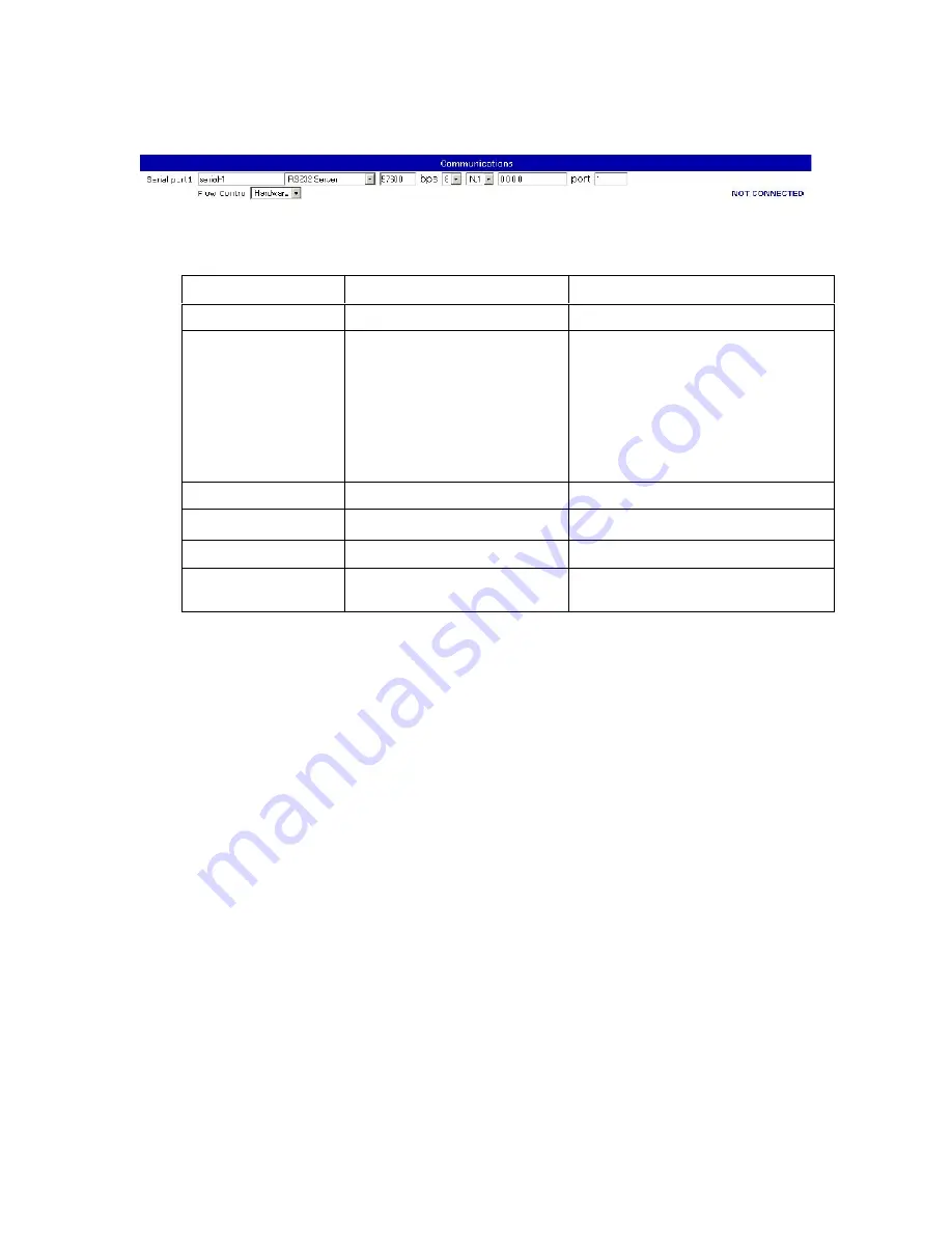
The Communications screen allows the user to configure the N-111’s serial port.
The serial port has a user-settable text label identifying it for user documentation
purposes. This string can be up to 15 characters long.
The serial mode drop-down menu allows the user to select both the hardware interface
and the software behavior of the serial port. The hardware mode of the port can be
selected between RS232, RS485 in 4 wire mode, and RS485 in 2 wire mode, to control
the hardware behavior of the serial output pins. RS232 mode ports can be connected to
customer equipment with any standard serial cable. RS485 2 wire or 4 wire ports will
need to use a custom header to connect to customer equipment.
The software mode can be selected from server or client mode. “Disabled” mode can be
selected to leave a port with no connection to the network.
The hardware baud rate for each port can be selected from 0 to 57600 bps. This
controls the rate at which the hardware port receives and transmits data. It does not
affect the rate at which information is transmitted over the network.
IP address specifies the address of the target N-111 on which there will be a port which
this serial port is to link to. This address may be up to 15 characters long and must be in
dotted-quad format. An IP address is required for client mode and must contain the
network IP address of the device the client will connect to. In server mode the IP
address is optional. If an IP address is provided in server mode the server port will only
accept incoming connections from that address.
Setting
Default Value
Range
Name
“aux-N”
15 characters
Mode
RS232 Server
Disabled
RS232 Server
RS485-4 Wire Server
RS485-2 Wire Server
RS232 Client
RS485-4 Wire Client
RS485-2 Wire Client
Speed
57600
0-57600
IP
“0.0.0.0”
15 characters
Port
1-4
1-4
Flow Control
Hardware
Hardware
None
Summary of Contents for N-111
Page 1: ...1 Net I O N 111 User s Manual Revision 8 2 2013...
Page 4: ...4 Ethernet Serial Aux Alarm...
Page 5: ...5 1 Introduction Overview Package Checklist Product Features Product Specifications...
Page 8: ...8 2 Getting Started Panel Layout Connecting the Hardware LED indicators Real time clock...
Page 11: ...11...
Page 15: ...15 3 Initial IP configuration Factory default IP Reset sequence NTP timeserver configuration...
Page 47: ...47 A Pinouts and connectors Power Ethernet Serial Aux Alarm...
Page 51: ...51...


