Technical data
Assembly Instructions EN
PG12 I PG16 I PG20
Edition 08/2020
Rev. 2.0
15–48
3 Technical data
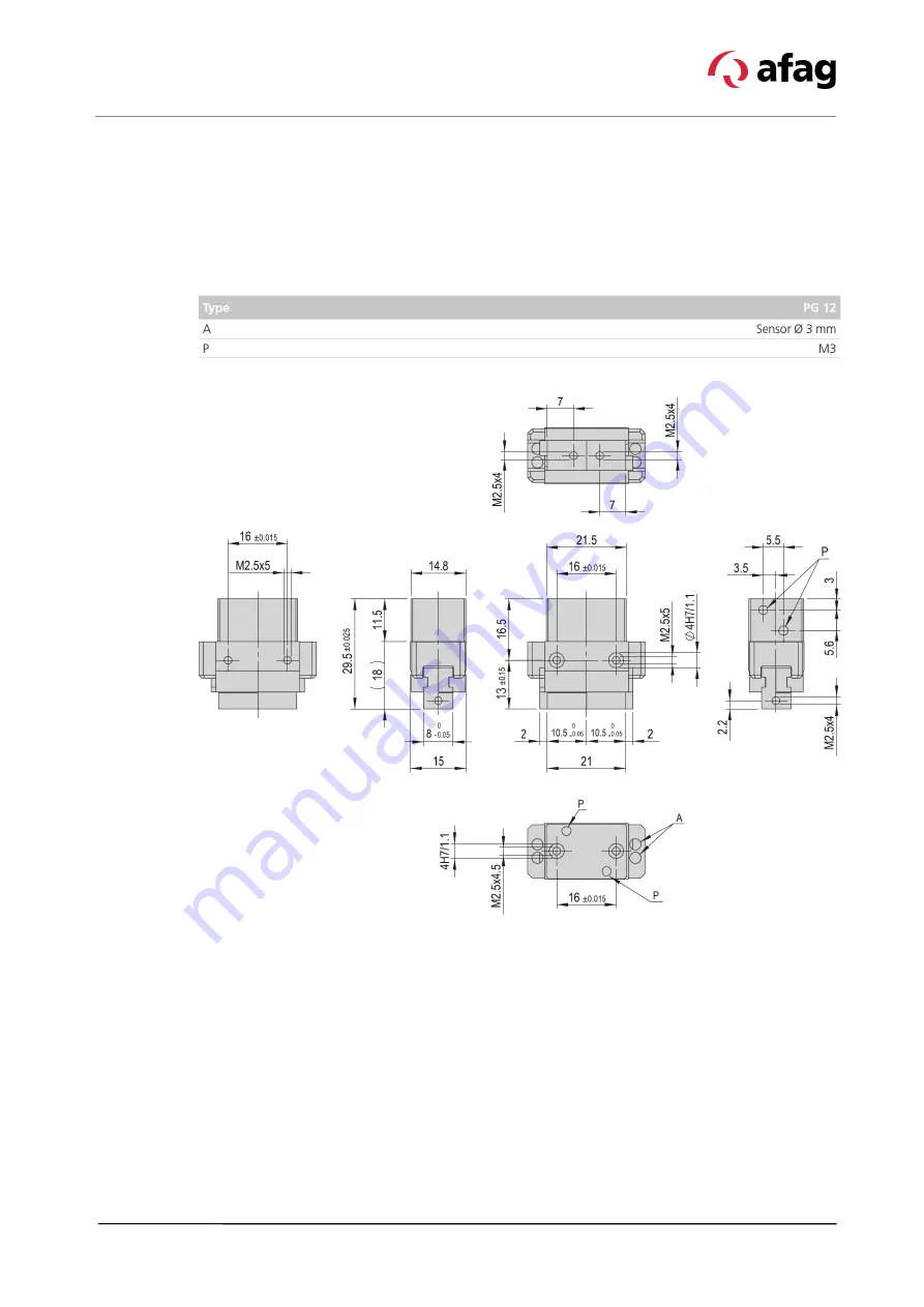
3.1 Precision gripper PG12
3.1.1 Dimension drawing PG12
Fig. 1
Dimensional drawing of precision gripper PG12
Page 1: ...6 I PG20 Edition 08 2020 Rev 2 0 1 48 Assembly and operating instructions Precision gripper PG12 I PG 16 I PG 20 Translation of the Original Assembly Instructions EN PG 12 Order no 50332223 PG 16 Order no 50332224 PG 20 Order no 50332225 ...
Page 2: ...Afag team Subject to modifications The precision grippers have been designed by Afag Automation AG according to the state of the art Due to the constant technical development and improvement of our products we reserve the right to make technical changes at any time Copyright 2020 Afag Automation AG All contents of the present assembly and operating instructions in particular the texts photographs ...
Page 3: ... 11 2 5 1 Personnel qualification 11 2 6 Personal protective equipment PPE 12 2 7 Changes modifications 12 2 8 General hazards residual risks 13 2 8 1 General hazards at the workplace 13 2 8 2 Danger due to electricity 14 2 8 3 Danger due to pneumatics 14 2 8 4 Mechanical hazards 14 3 Technical data 15 3 1 Precision gripper PG12 15 3 1 1 Dimension drawing PG12 15 3 1 2 Technical data PG12 16 3 1 3...
Page 4: ...on 33 7 Commissioning 34 7 1 Safety instructions for commissioning 34 7 2 Preparatory activities for commissioning 35 7 2 1 Installation of the inductive sensors 35 7 2 2 Installation of the initiators 35 7 3 Commissioning of the modules 36 7 4 Setting up retrofitting 36 8 Fault elimination 37 8 1 Safety instructions for troubleshooting 37 8 2 Fault causes and remedy 37 9 Maintenance and repair 38...
Page 5: ...pper s service life The illustrations in this manual shall provide you with a basic understanding of the module and may vary from the actual design of your module 1 2 Explanation of symbols The safety notes are marked by a pictogram and a signal word The safety notes describe the extent of the hazard DANGER Danger This safety note indicates an imminently hazardous situation which if not avoided wi...
Page 6: ...s Where applicable the following standardised symbols are used in this manual to point out the various potential health risks Warning Dangerous electrical voltage Warning Risk of injury from contact with hot surfaces Warning Risk of hand and finger injury due to uncontrolled movements of components Warning Magnetic field Warning Back injury due to heavy lifting Warning Risk of injury as a result o...
Page 7: ...y Wear parts are excluded from the warranty The customer is entitled to a product free of defects This does also apply to defective accessories and wear parts Normal wear and tear are excluded from the warranty The warranty covers the replacement or repair of defective Afag parts Further claims are excluded The warranty shall expire in the following cases Improper use of the module Non observance ...
Page 8: ...ity No changes shall be made to the precision gripper unless described in this instructions manual or approved in writing by Afag Automation AG Afag Automation AG accepts no liability for unauthorized changes or improper assembly installation commissioning operation maintenance or repair work ...
Page 9: ...ollow the directions and safety instructions given in this instructions manual may result in serious hazards 2 2 Intended use The precision grippers series is designed for the shock free linear movement of permanently mounted loads in non explosive environments and in the ambient and operating specially conditions defined for these modules The precision grippers are used in automation systems The ...
Page 10: ...ave the necessary professional qualifications and experience are familiar with the basic rules regarding occupational safety and accident prevention have been instructed in the correct handling of the precision gripper have read and understood these assembly instructions The operating company is also required to monitor on an ongoing basis that the personnel work safely considering any potential h...
Page 11: ... use of the precision gripper thus exposing himself and others to the risk of serious injury Therefore only qualified personnel may be permitted to carry out the described activities on the precision gripper Persons whose ability to react is restricted due to the intake of medication or the like must not interact with the precision gripper These installation instructions are intended for skilled p...
Page 12: ... respective mandatory signs Protective clothing is a close fitting clothing specifically designed to protect personnel from hazards during work Protective gloves are specifically designed to protect the personnel against hand injuries such as cuts abrasion burns Safety shoes are specifically designed to protect the personnel against foot injuries from crushing falling objects or slipping on slippe...
Page 13: ...he personnel danger to life and limb of the operator or third parties on the precision grippers themselves property damage Always keep the assembly instructions ready at hand at the workplace Please also observe the general and local regulations on accident prevention and environmental protection Observe the safety information sheet for the precision grippers WARNING Danger Do not use in unsuitabl...
Page 14: ...n or trained personnel under the supervision of a skilled electrician in accordance with all relevant electrical regulations WARNING Risks by the pneumatic system The pneumatic system can pose various hazards that can cause serious or fatal injuries if the work is carried out improperly Only qualified personnel may work with or on the pneumatic system The necessary personal protective equipment mu...
Page 15: ...cal data Assembly Instructions EN PG12 I PG16 I PG20 Edition 08 2020 Rev 2 0 15 48 3 Technical data 3 1 Precision gripper PG12 3 1 1 Dimension drawing PG12 Fig 1 Dimensional drawing of precision gripper PG12 ...
Page 16: ...Technical data 16 48 Assembly instructions EN PG12 I PG16 I PG20 Edition 08 2020 Rev 2 0 3 1 2 Technical data PG12 ...
Page 17: ...Technical data Assembly Instructions EN PG12 I PG16 I PG20 Edition 08 2020 Rev 2 0 17 48 3 1 3 Preferred combinations PG12 ...
Page 18: ...Technical data 18 48 Assembly instructions EN PG12 I PG16 I PG20 Edition 08 2020 Rev 2 0 3 1 4 Module stresses PG12 ...
Page 19: ...Technical data Assembly Instructions EN PG12 I PG16 I PG20 Edition 08 2020 Rev 2 0 19 48 3 2 Precision gripper PG16 3 2 1 Dimensional drawing PG16 Fig 2 Dimensional drawing of precision gripper PG16 ...
Page 20: ...Technical data 20 48 Assembly instructions EN PG12 I PG16 I PG20 Edition 08 2020 Rev 2 0 3 2 2 Technical data PG16 ...
Page 21: ...Technical data Assembly Instructions EN PG12 I PG16 I PG20 Edition 08 2020 Rev 2 0 21 48 3 2 3 Preferred combinations PG16 ...
Page 22: ...Technical data 22 48 Assembly instructions EN PG12 I PG16 I PG20 Edition 08 2020 Rev 2 0 3 2 4 Module stresses PG16 ...
Page 23: ...Technical data Assembly Instructions EN PG12 I PG16 I PG20 Edition 08 2020 Rev 2 0 23 48 3 3 Precision gripper PG20 3 3 1 Dimensional drawing PG20 Fig 3 Dimensional drawing of precision gripper PG20 ...
Page 24: ...Technical data 24 48 Assembly instructions EN PG12 I PG16 I PG20 Edition 08 2020 Rev 2 0 3 3 2 Technical data PG20 ...
Page 25: ...Technical data Assembly Instructions EN PG12 I PG16 I PG20 Edition 08 2020 Rev 2 0 25 48 3 3 3 Preferred combinations PG20 ...
Page 26: ...Technical data 26 48 Assembly instructions EN PG12 I PG16 I PG20 Edition 08 2020 Rev 2 0 3 3 4 Module stresses PG20 ...
Page 27: ...tion sheet must be read by every person who carries out work with and on the precision grippers Fig 4 Scope of delivery precision grippers PG12 PG16 and PG20 Unt PG 12 PG 16 PG 20 1 x Module PG 12 Module PG 16 Module PG 16 2 x Centering bushing ø4x2 mm Centering bushing ø5x2 5 mm Centering bushing ø7x3 1 x Mounting operating instruct Mounting operating instruct Mounting operating instruct CAUTION ...
Page 28: ... the precision grippers are stored for an extended period of time observe the following Store the precision gripper in the transport packaging Do not store the precision gripper outdoors or expose them to weather conditions The storage space must be dry and dust free Room temperature of the storage space 0 50 C Relative air humidity 90 non condensing Clean the precision gripper and protect the bla...
Page 29: ...upply and can be ordered separately The precision grippers have a repeatability accuracy of 0 01 mm and a turning precision of 0 05 mm The gripping forces are indicated in the corresponding table of the gripper type in this manual Precision grippers can be combined with other modules from the Afag modular system 5 3 Accessories PG 12 PG 16 PG 20 Centring bushing ø 4x2 mm Order no 50332257 Centring...
Page 30: ...re with the working area of the precision gripper When installing a precision gripper in an assembly system the system operator must provide the system with a protective device with a locked door safety circuit No liability can be assumed for damages caused by improper installation assembling work carried out by the operator Also observe the safety instructions in chap 2 Safety instructions in thi...
Page 31: ...osition The Afag module components are provided with a precise module centring which guarantees a high and repetitive accuracy of fit during installation operation and exchange of a module 6 2 1 Attachment The precision grippers can be mounted at the rear and the side Fig 6 Attachment of the precision gripper example For mounting use the centering sleeves chapter 4 2 included in the scope of deliv...
Page 32: ...ions Standard VDI 2230 Screw strength Category 8 8 Surface Galvanized blue oiled or greased Thread Tightening torque M2 0 3 0 35 Nm M2 5 0 5 0 73 Nm M3 1 1 1 4 Nm M4 2 6 3 3 Nm M5 5 2 6 5 Nm M6 9 0 11 3 Nm M8 21 6 27 3 Nm 6 3 Assembly of the gripper fingers 6 3 1 Example connection geometry gripper finger Fig 7 Connection geometry of gripper finger Example connection geometry gripper finger ...
Page 33: ... at the sides of the base body of the pneumatic gripper Fig 8 Pneumatic connections of the precision gripper Operating pressure 6 bar 2 Close air connections which are not used air tight before installing the module in a system Caution Carry out a leakage test Fig 9 Pneumatic diagram of precision gripper P1 P2 P1 open P2 close 1 Compressed air connection 4 One way restrictor 2 Maintenance unit 5 P...
Page 34: ...ve a complete view of the working area Persons within the working area may be injured When operating the precision gripper ensure a good overview of the entire working area Unauthorized persons must not stay within the working area during operation CAUTION Risk of injuries due to uncontrolled parts movements When the control unit is switched on signals from the control unit can lead to unintention...
Page 35: ... Tighten clamping screws Fig 10 1 slightly 4 Check the sensor for proper function Readjust the sensor if necessary 5 Tighten clamping screws Fig 10 1 The sensor is mounted 7 2 2 Installation of the initiators The opening and closing position can be checked with the initiators The initiators can be inserted on both sides in the black plier head You can decide yourself on which side the initiators a...
Page 36: ...out work The precision grippers are precision mechanical devices and must be handled with the necessary care and cleanliness during all work Commissioning may only be carried out by qualified personnel CAUTION Risk of injury due to incorrect operation of the system Incorrect operation during setup work on the machine can lead to unintentional starting of the precision gripper and cause injuries Se...
Page 37: ...ule to Afag for overhaul Check pneumatic connections and connect module correctly Open throttle non return valve Module audibly loses compressed air Leakage from compressed air connection Leakage from cylinder Check closures on air connections retighten if necessary Send module to AFAG WARNING Danger of injury due to faulty troubleshooting Poorly performed troubleshooting work can lead to serious ...
Page 38: ... maintenance activities can cause considerable damage to property and serious injury Only use qualified personnel to carry out the activities Always wear personal protective equipment when carrying out maintenance and repair work WARNING Risk of injuries due to uncontrolled parts movements Signals from the control system can trigger unintentional movements of the precision gripper and cause injury...
Page 39: ... Maintenance work Interval System On Off Remarks 1 Fasteners Checking After commissioning Off Check fastening elements for tight fit 2 Module Cleaning After commissioning Off Clean with a dry lint free cloth The precision gripper must not be sprayed Do not use aggressive cleaning agents 9 3 2 Further maintenance Further maintenance is not required if the ambient conditions listed below are complie...
Page 40: ...ir Viscosity range 9 11 mm2 s cST at 40 C ISO class VG 10 acc ISO 3448 NOTICE Risk of damage to property The operation of the gripper modules with oil lubricated compressed air causes the factory primary lubrication to be washed out Therefore it is absolutely essential that the gripper modules continue to be operated with oil lubricated compressed air in order to avoid damage to the rotary modules...
Page 41: ...precision grippers may only be replaced or repaired by AFAG AFAG does not guarantee modules that have not been repaired by AFAG CAUTION Risk of injury when removing the precision gripper from uncontrolled movements When dismounting the precision gripper from the machine there is a danger of uncontrolled movements Disconnect the media supply electrics before removing the grippers Disassembling shou...
Page 42: ...eparate the various components according to type of material and dispose of properly Scrap the metallic materials Hand over plastic parts for recycling Sort the rest of the components by their material properties and dispose of them accordingly WARNING Risk of injury from improper decommissioning and disposal Improperly carried out activities can result in considerable material damage and serious ...
Page 43: ...ards applied in particular EN ISO 12100 2010 Safety of machinery General design principles Risk assessment and risk reduction Note The partly completed machinery must not be put into service until the machinery into which it is to be incorporated has been declared in conformity with the provisions of Machinery Directive 2006 42 EC The manufacturer undertakes to transmit in response to a reasoned r...
Page 44: ...s 8 I Instructions 7 O Obligations and liability 10 Obligations of the operating company 10 Obligations of the personnel 11 Operation 37 Operator 11 P Packaging 28 Personal protective equipment PPE 12 Personnel qualifications 11 Personnel requirements 11 Protective clothing 12 Protective gloves 12 Q Qualified electrician 11 Qualified personnel 11 R Residual risks 13 S Safety instructions 9 38 Safe...
Page 45: ...sion gripper PG20 23 Fig 4 Scope of delivery precision grippers PG12 PG16 and PG20 27 Fig 5 Design of the precision gripper example 29 Fig 6 Attachment of the precision gripper example 31 Fig 7 Connection geometry of gripper finger 32 Fig 8 Pneumatic connections of the precision gripper 33 Fig 9 Pneumatic diagram of precision gripper 33 Fig 10 Installation of inductive sensors 35 Fig 11 Installati...
Page 46: ...46 48 Assembly instructions EN PG12 I PG16 I PG20 Edition 08 2020 Rev 2 0 ...
Page 47: ...Assembly Instructions EN PG12 I PG16 I PG20 Edition 08 2020 Rev 2 0 47 48 ...
Page 48: ...48 48 Assembly instructions EN PG12 I PG16 I PG20 Edition 08 2020 Rev 2 0 ...