R05.0
16/05/2019
Page 17
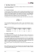
Adjustment should be carried out as follows:
Put a test part on the feeding track and switch on the control device. Use the turning
knob to reduce the feed rate of the Linear Feeder until the part on the feeder track is only
moving slowly. Maintain the control device setting and slowly unscrew the adjustment
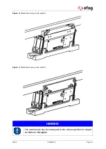
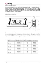
plate screws of a spring assembly of the Linear Feeder (see Fig 5). Check the feed rate
of the test part while loosening the screws. If the feed rate first increases briefly and then
starts to decrease on further loosening the screw, the Linear Feeder is not adjusted
properly, with the natural frequency slightly above the inducing frequency. The adjusting
plates have to be reset to the position they were in before loosening the screws.
If the feed rate increases when the screws are loosened and does not or only minimally
decrease when fully unscrewed, the Linear Feeder adjustment is too stiff, i.e. the natural
frequency is still too high. The adjustment plates have to be pushed downwards or, if the
weight difference is significant, a leaf spring may have to be removed. The test has to be
repeated afterwards.
If the feed rate decreases immediately on loosening the screws, the Linear Feeder ad-
justment is too soft. The adjustment plates then have to be pushed upwards or if neces-
sary, an additional leaf spring has to be fitted. The test has to be repeated afterwards.
When moving the adjustment plates, it should be kept in mind that the adjustment plates
always have to be horizontal and exactly opposite to each other.
Adjustment plates up
Natural frequency increases
Adjustment plates down
Natural frequency decreases
CAUTION
It is vital that the linear feeders be 'subcritically' adjusted (i.e. the
natural frequency must be about 5% above the exciter frequency)
as otherwise the magnet may overheat and burn out, and the
transport speed may decrease as soon as components are placed
upon the linear track.
To avoid the vibrating sections from subsiding, make sure to loosen the adjustment
plates of one spring assembly only at a time during frequency setting.
NOTE
The adjustment plates must be aligned horizontally. The top edg-
es must always be arranged opposite each other.

