Installation, assembly & setting
26 – 52
Assembly instructions EN
SA-1 I SA-1-FL
Edition 01/2021
Rev. 3.5
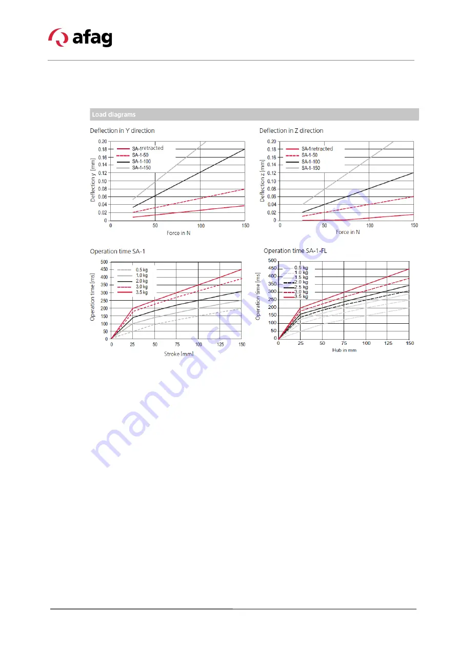
6.2.5 Load diagrams
Page 1: ...operating instructions Telescope spindle axis SA 1 I SA 1 FL Translation of the Original Assembly Instructions EN SA 1 050 Order no 50249011 SA 1 050 FL Order no 50471882 SA 1 100 Order no 50249013 SA 1 100 FL Order no 50471883 SA 1 150 Order no 50249014 SA 1 150 FL Order no 50471884 ...
Page 2: ... Your Afag team Subject to modifications The modules have been designed by Afag Automation AG according to the state of the art Due to the constant technical development and improvement of our products we reserve the right to make technical changes at any time Copyright 2021 Afag Automation AG All contents of the present assembly and operating instructions in particular the texts photographs and g...
Page 3: ...nts 10 2 5 1 Personnel qualification 10 2 6 Personal protective equipment PPE 11 2 7 Changes modifications 11 2 8 General hazards residual risks 12 2 8 1 General hazards at the workplace 12 2 8 1 Mechanical hazards 13 2 8 2 Danger due to electricity 13 2 8 3 Noise hazards 13 2 8 4 Danger due to high temperatures 14 2 8 5 Safety labels warning symbols 14 3 Technical data 15 3 1 Dimension drawing SA...
Page 4: ... 6 5 1 Safety instructions for programming 35 6 5 2 Programming 35 7 Commissioning 36 7 1 Safety instructions for commissioning 36 7 2 Preparatory activities for commissioning 37 7 3 Commissioning of the modules 37 7 4 Setting up retrofitting 38 8 Fault elimination 39 8 1 Safety instructions for troubleshooting 39 8 2 Fault causes and remedy 40 9 Maintenance and Repair 41 9 1 General notes 41 9 2 ...
Page 5: ... axis service life The illustrations in this manual shall provide you with a basic understanding of the module and may vary from the actual design of your module 1 2 Explanation of symbols The safety notes are marked by a pictogram and a signal word The safety notes describe the extent of the hazard DANGER Danger This safety note indicates an imminently hazardous situation which if not avoided wil...
Page 6: ...rning Dangerous electrical voltage Warning Risk of injury from contact with hot surfaces Warning Risk of hand and finger injury due to uncontrolled movements of components Warning Magnetic field Warning back injury due to heavy lifting Warning Risk of injury as a result of parts being flung out Warning high noise levels 1 3 Additional symbols In these assembly instructions the following symbols ar...
Page 7: ...ag parts Further claims are excluded The warranty shall expire in the following cases Improper use of the module Non observance of the instructions regarding assembly commissioning operation and maintenance of the module Improper assembly commissioning operation and maintenance Repairs and design changes carried out without prior technical instructions of Afag Automation AG Removing the serial num...
Page 8: ...ies or in damage to the automation system or other material assets Failure to follow the directions and safety instructions given in this instructions manual may result in serious hazards 2 2 Intended use The telescope spindle axis series SA 1 and SA 1 FL is designed for the shock free linear movement of permanently mounted loads in non explosive environments and in the ambient and operating condi...
Page 9: ...nnel who have the necessary professional qualifications and experience are familiar with the basic rules regarding occupational safety and accident prevention have been instructed in the correct handling of the telescope spindle axis have read and understood these assembly instructions The operating company is also required to monitor on an ongoing basis that the personnel work safely considering ...
Page 10: ...rsonnel may be permitted to carry out the described activities on the telescope spindle axis Persons whose ability to react is restricted due to the intake of medication or the like must not interact with the telescope spindle axis These installation instructions are intended for skilled personnel installers system integrators maintenance personnel technicians electricians and operating personnel ...
Page 11: ...pective mandatory signs Protective clothing is a close fitting clothing specifically designed to protect personnel from hazards during work Protective gloves are specifically designed to protect the personnel against hand injuries such as cuts abrasion burns Safety shoes are specifically designed to protect the personnel against foot injuries from crushing falling objects or slipping on slippery s...
Page 12: ...e as well as when handling setting up and assembling 2 8 1 General hazards at the workplace The telescope spindle axis has been built according to the state of the art and the applicable health and safety requirements However improper use of the telescope spindle axis may cause the following hazards to the personnel danger to life and limb of the operator or third parties on the telescope spindle ...
Page 13: ...ts is required ensure that the work is carried out properly failure to do so will cause serious or fatal injuries Work on the machine s electrical equipment may only be performed by skilled electrician or trained personnel under the supervision of a skilled electrician in accordance with all relevant electrical regulations CAUTION Noise hazards The telescope spindle axis generates 68 dB A during f...
Page 14: ...rning symbols are attached at the following places Check regularly whether the safety labels warning symbols are still present and legible CAUTION Danger of injury from hot surfaces During continuous operation of the telescope spindle axis the surface of the axis heats up Before touching hot surfaces without protective gloves make sure they have cooled down to ambient temperature ...
Page 15: ...Technical data Assembly instructions EN SA 1 I SA 1 FL Edition 01 2021 Rev 3 5 15 52 3 Technical data 3 1 Dimension drawing SA 1 and SA 1 FL Fig 1 Dimension drawing telescope spindle axis ...
Page 16: ...Technical data 16 52 Assembly instructions EN SA 1 I SA 1 FL Edition 01 2021 Rev 3 5 3 2 Technical data SA 1 and SA 1 FL ...
Page 17: ... 17 52 3 3 Preferred combinations SA 1 and SA 1 FL AFAG accepts no liability for the attachment of third party modules to the telescope spindle axis Modules for attachment shall be selected to withstand full load operation of the telescope spindle axis and not exceed the payload ...
Page 18: ... according to the order key In addition to the assembly and operating instructions a safety information sheet is enclosed with each telescope spindle axis This information sheet must be read by every person who carries out work with and on the telescope spindle axis Unt SA 1 SA 1 FL 1 x Module SA 1 Module SA 1 FL 2 x Centering bushing ø 5x2 5 Centering bushing ø 5x2 5 2 x Centering bushing ø 7x3 C...
Page 19: ...elescope spindle axes are stored for an extended period of time observe the following Store the telescope spindle axis in the transport packaging Do not store the telescope spindle axes outdoors or expose them to weather conditions The storage space must be dry and dust free Room temperature of the storage space 0 50 C Relative air humidity 90 non condensing Clean the telescope spindle axis and pr...
Page 20: ... to dip into the working area and to leave it again completely The bracket Fig 3 2 is moved along a linear guide Fig 3 3 vis à vis the base body Fig 3 1 A ball type linear drive Fig 3 4 with a spindle nut mounted on the bracket Fig 3 2 transforms the rotary movement in a linear movement The spindle is driven by a servomotor Fig 3 7 via a toothed belt back gear Fig 3 5 or a torsionally stiff coupli...
Page 21: ...omotor 11 320VDC 060W 60 x R x x 50495878 7 Encoder cable G6 5m 0 0 SE Power 50100693 8 Encoder cable G8 3m 0 0 SE 48 50341479 9 Encoder cable G8 5m 0 0 SE 48 50341480 10 Encoder cable G12 3m 0 0 50332416 11 Encoder cable G12 5m 0 0 50338975 12 Encoder cable M10 5m 0 Open SE Power 50219768 13 Motor cable M11 3m 0 0 SE24 48 50338982 14 Motor cable M11 5m 0 0 SE24 48 50338983 15 Programming cable SE...
Page 22: ...st provided an appropriate enclosure or safety barrier No liability for damages can be assumed for damages caused by improper installation assembling work on the part of the operator Also observe the safety instructions in Chapter 2 Safety instructions in this manual CAUTION Risk of injury when installing the telescope spindle axis in a system Improperly performed work can lead to injuries and dam...
Page 23: ...n the scope of delivery must be used for fastening the module Chapter 6 2 3 Fig 4 Mounting holes M4 on the back of the housing 6 2 2 Tightening torques Use screws with the following minimum specifications for mounting Standard VDI 2230 Screw strength Category 8 8 Surface Galvanized blue oiled or greased Thread Tightening torque M2 0 3 0 35 Nm M2 5 0 5 0 73 Nm M3 1 1 1 4 Nm M4 2 6 3 3 Nm M5 5 2 6 5...
Page 24: ...t grid and centering bushings Use the centring bushings included in the scope of delivery for positioning Insert the centering bushings in two diagonally opposite holes of the attachment grid SA 1 and SA 1 FL Base body Bracket Hole grid 30 x 30 mm 20 x 30 mm Thread Bore M4 M3 Centering bushing H7 Ø 7x3 mm Ø 5x2 5 mm ...
Page 25: ...Installation assembly setting Assembly instructions EN SA 1 I SA 1 FL Edition 01 2021 Rev 3 5 25 52 6 2 4 Load on the telescope spindle axis The following telescope spindle axis loads apply to assembly ...
Page 26: ...Installation assembly setting 26 52 Assembly instructions EN SA 1 I SA 1 FL Edition 01 2021 Rev 3 5 6 2 5 Load diagrams ...
Page 27: ...nt left right or axial Fig 5 Possible arrangement of the servomotor 6 3 1 Arrangement options Fig 6 Mounting the motor RIGHT AXIAL 1 Base body 6 Coupling housing 2 Bracket 7 Servo motor 3 Linear guide 8 Holding brake 4 Ball screw axis 9 Motor Encoder connector 5 Toothed belt housing 10 Reference switch connector 10 1 8 4 5 6 7 9 2 3 Motor RIGHT Motor AXIAL ...
Page 28: ...mount the cover Fig 7 1 3 Loosen the 4 x screws M3x6 Fig 7 3 4 Rotate the housing Fig 7 4 90 to the left or right swivel 5 Tighten 4 x screws Fig 7 3 M3x6 with a tightening torque of 1 4 Nm 6 Mount and fasten the cover Fig 7 1 7 Reassemble all necessary cables 8 Connect the controller unit The adjustment of the motor position is completed After adjusting the motor position the telescope spindle ax...
Page 29: ...eference or Emergency Stop switch Pin Signal 1 5 24 V DC 3 GND 4 Signal PNP We recommend using the Afag standard cables specified in the accessories The motor connectors can be rotated 180 Proceed as described below 1 Loosen the screws 2 Rotate the motor connectors 3 Tighten the screws again Fig 8 Adjusting the motor position SA 1 SA 1 FL Base body A 1 U B 5 V C 2 W D 3 GND Motor 6 Brake 4 Brake S...
Page 30: ...elescope spindle axis type SE 48 Further information on the control units can be found in the technical product catalogue Chapter Controller or in the respective instructions on our website www afag com 6 4 1 SE 48 Controller The plant operator is responsible for the safety of the controller as the telescope spindle axis is controlled by the plant control unit Fig 9 Table of controllers SE 48 ...
Page 31: ...Installation assembly setting Assembly instructions EN SA 1 I SA 1 FL Edition 01 2021 Rev 3 5 31 52 Fig 10 Dimensions Controllers SE 48 ...
Page 32: ...nstallation assembly setting 32 52 Assembly instructions EN SA 1 I SA 1 FL Edition 01 2021 Rev 3 5 6 4 2 SE Power for control cabinet mounting Fig 11 Overview table SE Power for control cabinet mounting ...
Page 33: ...Installation assembly setting Assembly instructions EN SA 1 I SA 1 FL Edition 01 2021 Rev 3 5 33 52 Fig 12 Installation SE Power for control cabinet mounting ...
Page 34: ...Installation assembly setting 34 52 Assembly instructions EN SA 1 I SA 1 FL Edition 01 2021 Rev 3 5 6 4 3 Servo controller ...
Page 35: ...r unit manufacturer WARNING Risk of injury from unexpected movements and ejected parts due to incorrect programming Incorrect programming can cause uncontrolled movements of the telescope spindle axis resulting in injury and damage to property The telescope spindle axis can also drive into the stop without braking so that people can be injured by ejected parts Have programming carried out by quali...
Page 36: ...n the telescope spindle axis make sure that the control unit is switched off and secured against being switched on again CAUTION Danger of injury in the working area of the telescope spindle axis Due to the decentralised control system the operator of the telescope spindle axis must not necessarily stand next to the module during operation so that he may not have a complete view of the working are...
Page 37: ...ction of the encoder and the reference switch 6 Perform test run Start with slow movements Then continue under normal operating conditions Commissioning is completed CAUTION Danger due to missing protective devices Operating the telescope spindle axis without suitable safety devices can lead to considerable damage to property and injuries Protective covers safety doors or other safety devices must...
Page 38: ...bserve the operating instructions CAUTION Risk of injury in case of power failure In the event of a power failure during installation and setup work the telescope spindle axis can slide down without a motor brake and injure people The system operator must ensure that no employees are in the danger zone during installation and set up work CAUTION Risk of injury due to mounted components The telesco...
Page 39: ...shooting work can lead to serious injuries and damage to property Only use trained specialist personnel for troubleshooting All work on the telescope spindle axis must be carried out with the power supply cut off NOTICE Danger of material damage due to vibrations on the drive Risk of damage to the telescope spindle axis and attached components if the moving part of the module oscillates very stron...
Page 40: ...le axis does not move Drive incorrectly connected Motor disconnection Drive defective Check terminal assignment and correct if necessary Carry out function check Check motor cable Have the drive replaced by AFAG Malfunction during operation Fault Possible cause Remedy The telescope spindle axis oscillates very strong vibrations at the drive Control parameters incorrectly adjusted Readjust the para...
Page 41: ...considerable damage to property and serious injury Only use trained specialist personnel to carry out the activities Always wear personal protective equipment when carrying out maintenance and repair work WARNING Risk of injuries due to uncontrolled parts movements When the control system is switched on the telescope spindle axis can make unpredictable movements and cause injury or damage to prope...
Page 42: ...point Maintenance work Interval System On Off Remarks 1 Safety labels warning symbols check 1 x Month Off Check for damage legibility cleanliness 2 Module Cleaning As required Off With lint free dry cloth Do not spray module with water do not use aggressive cleaning agents 3 Spindle gear Lubricating Every 4 million load cycles Off Recommended lubricant Klüber Microlube GBU Y 131 Alternatively Type...
Page 43: ...control cannot be started up again 3 Remove the blind plug Fig 14 1 from the spindle cover 4 Screw the grease gun attachment see accessories to the grease gun 5 Lubricate the spindle with the grease gun 1 1 5 g Recommended lubricant Klüber Microlube GBU Y 131 Alternative Type KP 1 N DIN 51502 Type NLGI Class 1 DIN 51818 6 Refit the blind plug The lubrication is completed After lubrication perform ...
Page 44: ...of carriage Procedure for lubricating the linear guide 1 Move the axis to the front end position max stroke 2 Switch off the control and use a lockout device to make sure that the control cannot be started up again 3 Remove grease residues or dirt from the guide rail 4 Lubricate the guideways of the linear guide Fig 15 1 so that an even lubricating film is applied 5 Lubricate the carriage with the...
Page 45: ...er the official warranty period has expired wear parts toothed belts can be replaced by the customer The appropriate toothed belts must be ordered from the manufacturer of the telescope spindle axis Other defective module parts may only be replaced by AFAG NOTICE Danger of corrosion damage when used in an ionized air environment When used in an ionized air environment e g coronising in high voltag...
Page 46: ...ious components according to type of material and dispose of them properly Scrap the metallic materials Hand over plastic parts for recycling Sort the rest of the components by their material properties and dispose of them accordingly WARNING Risk of injury due to improper decommissioning and disposal Improperly carried out activities can result in considerable material damage and serious injury O...
Page 47: ... 2014 30 EU Electromagnetic Compatibility Directive EMC 2014 35 EU Low Voltage Directive LVD EN ISO 12100 2010 Safety of machinery General design principles Risk assessment and risk reduction DIN EN 60204 1 2018 Safety of machinery Electrical equipment of machines Part 1 General requirements Note The partly completed machinery must not be put into service until the machinery into which it is to be...
Page 48: ... 7 I Instructions 6 O Obligations and liability 9 Obligations of the operating company 9 Obligations of the personnel 10 Operation 39 Operator 10 P Packaging 19 Personal protective equipment PPE 11 Personnel qualifications 10 Personnel requirements 10 Protective clothing 11 Protective gloves 11 Q Qualified electrician 10 Qualified personnel 10 R Residual risks 12 S Safety instructions 8 41 Safety ...
Page 49: ...e arrangement of the servomotor 27 Fig 6 Mounting the motor RIGHT AXIAL 27 Fig 7 Adjusting the motor position 28 Fig 8 Adjusting the motor position 29 Fig 9 Table of controllers SE 48 30 Fig 10 Dimensions Controllers SE 48 31 Fig 11 Overview table SE Power for control cabinet mounting 32 Fig 12 Installation SE Power for control cabinet mounting 33 Fig 13 Telescope spindle axis 42 Fig 14 Telescope ...
Page 50: ...50 52 Assembly instructions EN SA 1 I SA 1 FL Edition 01 2021 Rev 3 5 ...
Page 51: ...Assembly instructions EN SA 1 I SA 1 FL Edition 01 2021 Rev 3 5 51 52 ...
Page 52: ...52 52 Assembly instructions EN SA 1 I SA 1 FL Edition 01 2021 Rev 3 5 ...