Installation, assembly & setting
Assembly instructions EN
SA-3 I SA-3-FL I SA-6 I SA-6-FL
Edition 01/2021
Rev. 4.5
27–56
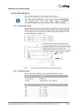
6.2 Assembly & attachment
The telescope spindle axis can be installed in any position.
In the case of vertical installation, the servomotor must have a
holding brake
that prevents the axle from falling when de-energised!
The telescope spindle axis must be earthed when installed in a system!
6.2.1 Fastening the module
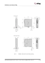
The telescope spindle axis can be installed in any position. The fixing holes (M4
for SA-3 and SA-3-FL) and (M6 for SA-6 and SA-6-FL) are located on the back
of the housing. The centring sleeves included in the scope of delivery must be
used for fastening (
Chapter 6.2.1).
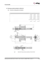
Fig. 5
Mounting holes (M4 and/or M6) on the back of the housing
6.2.2 Tightening torques
Use screws with the following minimum specifications for mounting:
Standard
VDI 2230
Screw strength
Category 8.8
Surface
Galvanized blue, oiled or greased
Thread
Tightening torque
M3
1.1 … 1.4 Nm
M4
2.6 … 3.3 Nm
M5
5.2 … 6.5 Nm
M6
9.0 … 11.3 Nm
M8
21.6 … 27.3 Nm
(X)
Bracket
The module may only be fastened on the underside!
The special M4x18 screws on the SA-3 and SA-3-FL
extension arms and M4x20 on the SA-6 and SA-6-FL are used
to attach extension modules to the extension slide.
When determining the screw length, make sure that the screw-
in depth of 7 mm (SA-3) or 12 mm (SA-6) is not exceeded!
Summary of Contents for 50113773
Page 54: ...54 56 Assembly instructions EN SA 3 I SA 3 FL I SA 6 I SA 6 FL Edition 01 2021 Rev 4 5 ...
Page 55: ...Assembly instructions EN SA 3 I SA 3 FL I SA 6 I SA 6 FL Edition 01 2021 Rev 4 5 55 56 ...
Page 56: ...56 56 Assembly instructions EN SA 3 I SA 3 FL I SA 6 I SA 6 FL Edition 01 2021 Rev 4 5 ...


