background image


Assembly Instructions EN  


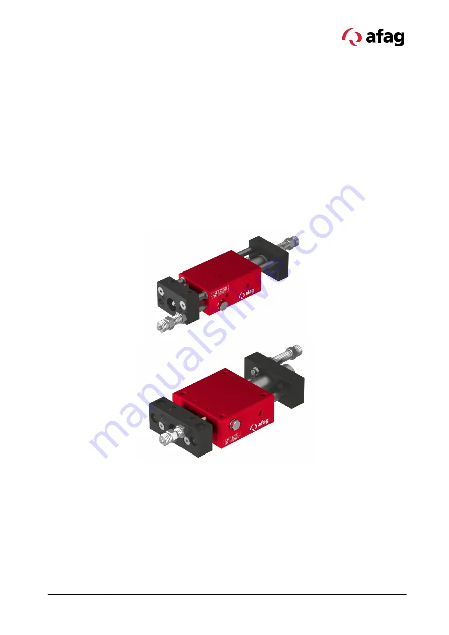
LM 12  I  LM 16  


Edition 11/2020  

  Rev. 2.5 

1–52


Assembly and operating instructions 


Linear Modules 

LM 12  

 LM 16 


Translation of the Original Assembly Instructions EN


LM 12/30 

  Order No.: 11010377 


LM 12/60 

  Order No.: 11010378 


LM 12/90 

  Order No.: 11010379 


LM 16/30 

  Order No.: 11001864 


LM 16/60 

  Order No.: 11001865 


LM 16/90 

  Order No.: 11001866 

Summary of Contents for 11001864

Page 1: ...bly and operating instructions Linear Modules LM 12 I LM 16 Translation of the Original Assembly Instructions EN LM 12 30 Order No 11010377 LM 12 60 Order No 11010378 LM 12 90 Order No 11010379 LM 16 30 Order No 11001864 LM 16 60 Order No 11001865 LM 16 90 Order No 11001866 ...

Page 2: ...g team Subject to modifications The linear modules have been designed by Afag Automation AG according to the state of the art Due to the constant technical development and improvement of our products we reserve the right to make technical changes at any time Copyright 2020 Afag Automation AG All contents of the present assembly and operating instructions in particular the texts photographs and gra...

Page 3: ...ersonnel qualification 11 2 6 Personal protective equipment PPE 12 2 7 Changes and modifications 12 2 8 General hazards residual risks 13 2 8 1 General hazards at the workplace 13 2 8 2 Danger due to mechanical hazards 13 2 8 3 Danger due to electricity 14 2 8 4 Danger due to pneumatic system 14 2 8 5 Danger due to noise emission 14 3 Technical data 15 3 1 Linear module LM 12 15 3 1 1 Dimension dr...

Page 4: ...36 7 1 Safety instructions for commissioning 36 7 2 Preparatory activities for commissioning 37 7 2 1 Adjusting the shock absorbers shock absorber SD 08 06 37 7 2 2 Setting of the lifting and stop screws 38 7 3 Commissioning of the modules 39 8 Fault elimination 40 8 1 Safety instructions for troubleshooting 40 8 2 Fault causes and remedy 40 9 Maintenance and repair 41 9 1 General notes 41 9 2 Saf...

Page 5: ...Table of contents Assembly Instructions EN LM 12 I LM 16 Edition 11 2020 Rev 2 5 5 52 10 3 Disposal 47 11 Declaration of incorporation 48 ...

Page 6: ...life The illustrations in this manual shall provide you with a basic understanding of the module and may vary from the actual design of your module 1 2 Explanation of symbols The safety notes are marked by a pictogram and a signal word The safety notes describe the extent of the hazard DANGER Danger This safety note indicates an imminently hazardous situation which if not avoided will result in de...

Page 7: ...tential health risks Warning Dangerous electrical voltage Warning Risk of injury from contact with hot surfaces Warning Risk of hand and finger injury due to uncontrolled movements of components Warning Magnetic field Warning Risk of injury as a result of parts being flung out Warning High noise levels 1 3 Additional symbols In these assembly instructions the following symbols are used to highligh...

Page 8: ...rts Further claims are excluded The warranty shall expire in the following cases Improper use of the module Non observance of the instructions regarding assembly commissioning operation and maintenance of the module Improper assembly commissioning operation and maintenance Repairs and design changes carried out without prior technical instructions of Afag Automation AG Removing the serial number f...

Page 9: ...s 2 2 Intended use The linear module series is designed for the shock free linear movement of permanently mounted loads in non explosive environments and in the ambient and operating specially conditions defined for these modules Chapter 3 Technical data The modules are designed exclusively for the linear movement of loads in any position The maximum admissible loads at the front plate are LM 12 0...

Page 10: ...have the necessary professional qualifications and experience are familiar with the basic rules regarding occupational safety and accident prevention have been instructed in the correct handling of the linear module have read and understood these assembly instructions The operating company is also required to monitor on an ongoing basis that the personnel work safely considering any potential haza...

Page 11: ...use of the linear modules thus exposing himself and others to the risk of serious injury Therefore only qualified personnel may be permitted to carry out the described activities on the linear modules Persons whose ability to react is restricted due to the intake of medication or the like must not interact with the linear module These installation instructions are intended for skilled personnel in...

Page 12: ...spective mandatory signs Protective clothing is a close fitting clothing specifically designed to protect personnel from hazards during work Protective gloves are specifically designed to protect the personnel against hand injuries such as cuts abrasion burns Safety shoes are specifically designed to protect the personnel against foot injuries from crushing falling objects or slipping on slippery ...

Page 13: ...anger to life and limb of the operator or third parties on the linear modules themselves property damage Always keep the assembly instructions ready at hand at the workplace Please also observe The general and local regulations on accident prevention and environmental protection Observe the safety information sheet for the linear module 2 8 2 Danger due to mechanical hazards WARNING Danger Do not ...

Page 14: ...regulations WARNING Risks by the pneumatic system The pneumatic system can pose various hazards that can cause serious or fatal injuries if the work is carried out improperly Work on pneumatic systems may only be carried out by a specialist or by instructed persons under the direction and supervision of a specialist in accordance with the applicable regulations CAUTION Risk of noise induced hearin...

Page 15: ...Technical data Assembly Instructions EN LM 12 I LM 16 Edition 11 2020 Rev 2 5 15 52 3 Technical data 3 1 Linear module LM 12 3 1 1 Dimension drawing LM 12 Fig 1 Dimensional drawing LM 12 ...

Page 16: ...Technical data 16 52 Assembly instructions EN LM 12 I LM 16 Edition 11 2020 Rev 2 5 3 1 2 Technical data LM 12 ...

Page 17: ...Technical data Assembly Instructions EN LM 12 I LM 16 Edition 11 2020 Rev 2 5 17 52 3 1 3 Preferred combinations LM 12 ...

Page 18: ...Technical data 18 52 Assembly instructions EN LM 12 I LM 16 Edition 11 2020 Rev 2 5 3 1 4 Module loads LM 12 ...

Page 19: ...Technical data Assembly Instructions EN LM 12 I LM 16 Edition 11 2020 Rev 2 5 19 52 3 2 Linear module LM 16 3 2 1 Dimensional drawing LM 16 Fig 2 Dimensional drawing LM 16 ...

Page 20: ...Technical data 20 52 Assembly instructions EN LM 12 I LM 16 Edition 11 2020 Rev 2 5 3 2 2 Technical data LM 16 ...

Page 21: ...Technical data Assembly Instructions EN LM 12 I LM 16 Edition 11 2020 Rev 2 5 21 52 3 2 3 Preferred combinations LM 16 ...

Page 22: ...Technical data 22 52 Assembly instructions EN LM 12 I LM 16 Edition 11 2020 Rev 2 5 3 2 4 Module loads LM 16 ...

Page 23: ...d storage as well as during handling adjustment and assembly Fig 3 Linear modules in original packaging and unpacked Also observe the safety instructions in Chap 2 Safety instructions in this manual CAUTION Risk of injury when unpacking by falling out of the linear modules The linear modules are packed in the original cardboard box If incorrectly handled the modules may fall out during unpacking a...

Page 24: ...d on the linear module Pcs LM 12 und LM 16 1 x Linear module 1 x Stop screws AS 08 25 2 x Stop screws AS 08 40 2 x Centering bushing Ø 9x4 mm 1 x Assembly instructions Variants of the linear modules The standard equipment includes two stop screws one AS 08 40 Fig 4 1 and one AS 08 25 Fig 4 2 for end position adjustment Fig 4 Linear module example The base plate can be used to create a portal modul...

Page 25: ...e following conditions must be complied with for transport and storage Storage temperature 0 50 C Relative air humidity 90 non condensing 4 4 Packaging The linear modules are transported in the transport packaging of AFAG Automation AG If no AFAG packaging used the linear module must be packed so that they are protected against shock and dust NOTICE Risk to the environment due to incorrect disposa...

Page 26: ...ore the linear module in the transport packaging Do not store the linear module outdoors or expose them to weather conditions The storage space must be dry and dust free Room temperature of the storage space 0 50 C Relative air humidity 90 non condensing Clean the linear module and protect the blank metal parts against corrosion using the appropriate means Protect the linear module from dirt and d...

Page 27: ...4 For sensing the end positions the stop screw can be fitted with an initiator holder and an initiator 6 5 mm not included in the scope of delivery Section 5 3 Accessories 5 2 Product description The linear modules LM 12 and LM 16 are pneumatically operated devices for longitudinal movements with a stroke of 0 90 mm All modules are delivered ready for installation according to customer order A dou...

Page 28: ...ch 6 5 mm 11004995 8 Proximity switch INI 8x8x38 5 Sn1 5 PNP NO M8x1 50428013 9 Holder proximity switch 8x8 mm 11004997 10 Shock absorber SD M8x1 2 11004990 5 3 2 Accessories LM 16 No Denomination Order number 1 Base plate Technical catalogue 2 Stop L bar Technical catalogue 3 Angle plate Technical catalogue 4 Connection plates Technical catalogue 5 Stop pins Technical catalogue 6 Proximity switch...

Page 29: ...on it must be ensured that the user cannot interfere with the working area of the linear module No liability can be assumed for damages caused by improper installation assembling work carried out by the operator Also observe the safety instructions in Chapter 2 Safety instructions in this manual CAUTION Danger of injury when installing the linear module in a system Improperly performed work can le...

Page 30: ...w Mounting of the LM 16 can be realized from below and from above LM 12 LM 16 Fig 9 Fastening options of the linear module Use the centering bushings included in the scope of delivery for positioning To do this insert the centering bushings in two diagonally opposite holes of the mounting grid CAUTION Danger of injury from sudden movements when installed in vertical position When installed in vert...

Page 31: ...ed as a slide it is mounted on the front plates M6 thread Fig 11 Linear module mounting on the end plates example LM 16 6 2 2 Tightening torques For assembling use screws with the following minimum specifications Standard VDI 2230 Screw strength Category 8 8 Surface Galvanized blue oiled or greased Thread Tightening torque M3 1 1 1 3 Nm M4 2 5 2 9 Nm M5 4 9 5 8 Nm M6 8 5 9 9 Nm ...

Page 32: ...st be closed airtight with the locking screws included in the scope of supply Fig 12 Pneumatic connection of the linear module 1 Linear module 2 Throttle check valve 3 Way valve standard 5 2 5 Maintenance unit P Air connection Minimum compressed air quality according to ISO 8573 1 2010 7 4 4 6 4 Proximity switch assembly WARNING Danger of explosion The proximity switches must not be used in a pote...

Page 33: ...tion monitoring during end position detection If the LED does not change its switching state during end position detection the proximity switch is defective and must be replaced Depending on the type of control the switching type PNP or NPN of the proximity switches must be determined The 6 5 mm and 8x8 mm proximity switches may only be used with the AS series stop screws Technical data for mounti...

Page 34: ... stop 3 Tighten the proximity switch holder Fig 14 1 slightly 4 Fit the plug Fig 14 4 5 Perform a function check The proximity switch 6 5 mm is mounted 6 4 2 Mounting of the proximity switch 8x8 mm Fig 15 Mounting of the proximity switch 8x8 mm For mounting the 8x8 mm proximity switch proceed as follows 1 Screw the proximity switch Fig 15 5 to the holder 7 with screws 6 2 Push the holder 7 with th...

Page 35: ...h must cover the hole of the proximity switch holder see arrow 6 5 Mounting of the angle plate connection plate The angle plate allows the combination of two LM 12 modules Fig 16 Mounting of the angle plate The connection plate allows the combination of an LM 16 with a gripper module GM 20 Fig 17 Mounting of the connection plate LM 16 GM 20 ...

Page 36: ... cables when the control unit is switched off Ensure that there are no persons tools in the working area CAUTION Risk of injury by reaching into the working area In normal operation it must be ensured that the user cannot reach into the working area of the linear modules The operator must provide suitable protective measures such as enclosures light barriers or de energising the drive CAUTION Dang...

Page 37: ...ews by means of shock absorbers Fig 18 Adjusting the shock absorbers Procedure for adjusting the shock absorbers 1 For the stop screw AS 08 25 and AS 80 40 press the stop pin max 3 mm completely in min 2 mm 2 Screw in the shock absorber Fig 18 1 until the pin protrudes at least 1 mm 3 Fasten the shock absorber with the fixing nut Fig 18 2 Das The maximum tightening torque of the nut must not excee...

Page 38: ...p pin is adjusted Fig 19 Stroke adjustment with stop pin Stroke adjustment with stop screws AS08 25 and AS 08 40 1 Adjust the stroke H by adjusting the stop screw Fig 20 3 2 Fasten the stop screw with the lock nut Fig 20 4 Stopping accuracy 1 0 01 mm The stroke with stop screws is adjusted Fig 20 Stroke adjustment with stop screws These stop screws can be combined with a proximity switch holder an...

Page 39: ...ing the modules for the first time 1 Observe the permissible technical values Chapter 3 Technical data Load Movement frequency Momentary load 2 Make sure that there are no persons or tools in the working area 3 Connect the cable to the linear module and the system control 4 Perform test run Start with slow movements then continue under normal operating conditions commissioning is completed ...

Page 40: ...eed too high Readjust shock absorber Replace shock absorber Retrofitting shock absorber Replace exhaust air throttle Setting the exhaust air throttle Load swings in the end position Lifting speed too high Suboptimal damping Unfavourable installation position Unfavourable LM type Setting the exhaust air throttle Optimise damper type and stroke Adaptation of the construction Use larger LM type Note ...

Page 41: ...apter 2 Safety instructions in this manual WARNING Danger of injury due to improper maintenance Improperly carried out maintenance activities can cause considerable damage to property and serious injury Only use qualified personnel to carry out the activities Always wear personal protective equipment when carrying out maintenance and repair work CAUTION Risk of injury due to pneumatic system When ...

Page 42: ...place if necessary Replace after max 5 Mio load changes recommended 2 Linear module Cleaning If required Off Pay attention to cleanliness of tape and profile surface Clean with a lint free dry cloth Do not rinse off do not use aggressive cleaning agents 3 Guideways and piston rods Cleaning and lubricating Monthly Off Only for use in ionised air environment Afag standard Staburax NBU8EP flat guidew...

Page 43: ...quantity 5 10 drops of oil per 1000 ltr Compressed air Viscosity range 9 11 mm2 s cST at 40 C ISO class VG 10 acc ISO 3448 NOTICE Risk of corrosion due to ionized air environment If the linear modules are used in an ionised air environment there is a risk that exposed parts could corrode Always grease exposed guides and piston rod regularly Recommendation monthly lubrication 9 3 1 NOTICE Risk of d...

Page 44: ...After expiry of the official warranty wearing parts can also be replaced by the customer himself using the corresponding wearing parts set 9 4 1 9 4 2 Wear parts set When replacing the wear parts all wear parts should be replaced together and properly so that the functional parts are not damaged Depending on the module stroke the wear part sets are different Make sure that the correct wear part se...

Page 45: ...e two dowel pins Fig 22 1 on the hand press 4 Remove the cylinder Fig 22 1 to the rear from the housing Fig 22 3 5 Clean the housing Fig 22 3 B Replacing wear parts 1 Insert the new cylinder Fig 22 1 into the housing Fig 22 3 2 Press 2x dowel pins Fig 22 1 into the housing 3 using a hand press 3 Insert the piston rod into the front plate Fig 22 2 and put on the washer 4 Hold the piston rod and scr...

Page 46: ... 23 1 on the hand press 4 Remove the cylinder Fig 23 1 to the rear from the housing Fig 23 3 5 Clean the housing Fig 23 3 B Replacing wear parts 1 Insert the new cylinder Fig 23 1 into the housing Fig 23 3 2 Press 2x dowel pins Fig 23 1 into the housing 3 using a hand press 3 Insert the piston rod into the front plate Fig 23 2 and put on the washer 4 Hold the piston rod and screw the nut Fig 23 7 ...

Page 47: ...ntle the linear module and separate the various components according to type of material and dispose of properly Scrap the metallic materials Hand over plastic parts for recycling Sort the rest of the components by their material properties and dispose of them accordingly WARNING Risk of injury from improper decommissioning and disposal Improperly carried out activities can result in considerable ...

Page 48: ... 1 7 4 2 Harmonised standards applied in particular EN ISO 12100 2010 Safety of machinery General design principles Risk assessment and risk reduction Note The partly completed machinery must not be put into service until the machinery into which it is to be incorporated has been declared in conformity with the provisions of Machinery Directive 2006 42 EC The manufacturer undertakes to transmit in...

Page 49: ... list of abbreviations 8 I Instructions 7 O Obligations and liability 10 Obligations of the operating company 10 Obligations of the personnel 11 Operation 40 Operator 11 P Packaging 25 Personal protective equipment PPE 12 Personnel qualifications 11 Personnel requirements 11 Protective clothing 12 Protective gloves 12 Q Qualified personnel 11 R Residual risks 13 S Safety instructions 9 41 Safety s...

Page 50: ...module 30 Fig 10 Mounting base from below Mounting base from above 31 Fig 11 Linear module mounting on the end plates example LM 16 31 Fig 12 Pneumatic connection of the linear module 32 Fig 13 Assembly of proximity switch 33 Fig 14 Mounting of the proximity switch 6 5 mm 34 Fig 15 Mounting of the proximity switch 8x8 mm 34 Fig 16 Mounting of the angle plate 35 Fig 17 Mounting of the connection pl...

Page 51: ...Assembly Instructions EN LM 12 I LM 16 Edition 11 2020 Rev 2 5 51 52 ...

Page 52: ...52 52 Assembly instructions EN LM 12 I LM 16 Edition 11 2020 Rev 2 5 ...

Reviews: