background image

E l e c t r o n i c   B r o a d c a s t   E q u i p m e n t

Pag. 4

     Xtreme

• Non tentare di fare alcun tipo di riparazione e/o regolazione che preve-
da la rimozione di coperchi o l'estrazione di schede.

• La rottura del fusibile interno all'alimentatore è sintomo di un guasto ge-
nerale dell'alimentatore stesso; la sua sostituzione non è consentita se non
da personale autorizzato. Si consiglia di rivolgersi direttamente al rivendi-
tore.

• Per l'eventuale riparazione rivolgersi direttamente al rivenditore e ri-
chiedere che vengano utilizzati ricambi originali. Il mancato rispetto di
quanto sopra 

può compromettere la sicurezza dell'apparecchio

.

• L'apparecchio deve essere collegato alla rete di alimentazione munita
di linea di terra regolamentare ed efficiente.

• L'esecuzione dell'impianto elettrico deve essere conforme alle norme
C.E.I. 64-8 "Norme degli impianti elettrici negli edifici civili".

• In fase di installazione è tassativo prevedere uno spazio libero intorno
all'apparecchio di almeno 1 cm per garantire un adeguata areazione.

N.B. L'apparecchio è costruito a regola d'arte. L'affidabilità
elettrica e meccanica sarà mantenuta efficiente se verrà fatto un
uso corretto dell'apparato e rispettate le prescrizioni di manu-
tenzione ove previste.

• Do not carry out repair and / or adjustment implying the removal of
covers or cards.

• The failure of a fuse inside the feeder reveals a general failure of
the feeder; it can be replaced only by authorized personnel. Contact
the dealer directly.

• For repair, please contact the dealer and ask for original spare parts. The
non-fulfilment of this instruction 

can jeopardize the equipment safety

.

• The equipment must be connected to the power mains which is
equipped with prescribed and efficient ground.

• The execution of the electric system must comply with the CEI rules
64-8 "Rules concerning the electric system in civil buildings".

• During the installation, a free space of 1 cm around the equipment must
expressly be considered in order to assure a suitable ventilation.

N.B. The equipment is workmanlike performed. The electric
and mechanic reliability will remain effective if the equipment
is correctly used and if the maintenance instructions, if any, are
complied with.

Summary of Contents for XTREME II

Page 1: ... Band Digital Audio Processor Operating Manual V 2 002 By Roberto Paganelli 20 02 2002 AEV S p A Via della Tecnica n 3 I 40050 Argelato Bologna Italy Tel 39 051 6634711 Fax 39 051 6634700 Web site http www aev net ...

Page 2: ...d assorbire i colpi che vengono rice vuti durante il trasporto Riportate sul pacco in rosso queste parole DELICATE INSTRUMENT FRAGILE Ricordate in numero RMA deve essere visibile anche sul pac co in caso contrario non verrà accettato Copyright AEV S p A 2001 Tutti i diritti riservati Nessuna parte di questa pubblicazione puó essere riprodotta trasmessa archiviata in un sistema di riferimento o tra...

Page 3: ...are qualsiasi operazione di pulizia e o manutenzione disinserite l apparecchio dalla rete di alimentazione elettrica ed attende re almeno 2 secondi come prescritto dalle normative che regolamentano la sicurezza In caso di guasto e o di cattivo funzionamento dell apparecchio spegner lo disconnettere l alimentazione non manometterlo e rivolgersi al riven ditore PRECAUTIONS ATTENTION The non fulfilme...

Page 4: ...ntire un adeguata areazione N B L apparecchio è costruito a regola d arte L affidabilità elettrica e meccanica sarà mantenuta efficiente se verrà fatto un uso corretto dell apparato e rispettate le prescrizioni di manu tenzione ove previste Do not carry out repair and or adjustment implying the removal of covers or cards The failure of a fuse inside the feeder reveals a general failure of the feed...

Page 5: ...tandsetzungs und oder Einstellungsarbeit durchführen die die Entfernung von Deckeln oder das Herausziehen von Karten vorsehen PRECAUTIONS ATTENTION lire toutes les instructions donnè es dans ce paragraphe car elles concernent la securitè l installation l emploi et l entretien Ne pas accomplir les régles et les prècautions spécifiques données dans ce manuel est une violation des règles de sécurité ...

Page 6: ... und wenn die Wartungsvorschriften falls vorgesehen beobachtet werden Ne pas chercher à faire une réparation et ou une mise à point qui rend nécessaire le déplacement des couvercles ou l extraction des fiches La rupture du fusible dans l alimentation signifie qu il y a une panne de l alimentation même son remplacement doit être fait seulement par le personnel autorisé On conseille de s adresser di...

Page 7: ...X coder parameters 15 Sec 4 4 System menu options 16 Sec 4 4 1 Setting date and time 17 Sec 4 4 2 Adjusting the display contrast 17 Sec 4 4 3 Operate ByPass 18 Sec 5 Edit Preset menu 18 Sec 5 1 BRILLIANCE 19 Sec 5 2 HF CLIPPING 19 Sec 5 3 PRESENCE 19 Sec 5 4 MID BASS BOOST 19 Sec 5 5 LOW BASS BOOST 19 Sec 5 6 BASS MATCHING 19 Sec 5 7 30Hz Hpf Filter 19 Sec 5 8 Voice Bass Boost 20 Sec 5 9 Gate Thre...

Page 8: ...n interface with any transmitter habitually used in any part of the world Xtreme II performs a high precision peak control restricting over modulation level to just 0 3 dB The Xtreme II audio processor dynamically controls the pre boost level it can never be heard to operate and produces a clear open brilliant sound which improves the original program Xtreme II s audio processing circuits produce ...

Page 9: ...AES EBU digital inputs and outputs 3 2 composite stereo outputs for FM version 4 RDS input if RDS coder option is not installed 5 SCA input for FM version 6 RDS output if RDS coder option is installed Sec 1 4 1 Analogue inputs outputs The analogue inputs are installed on two XLR female connectors located on the rear panel The input is 10 KΩ high impedance and the inputs accept signals up to 12dBu ...

Page 10: ...and 14dB Sec 1 4 5 SCA input A non balanced BNC connector for use with the SCA signal is also available on the input It can accept any type of 23 KHz subcarrier The subcarrier is mixed with MPX signals Accepted levels range between 0 and 14dB Sec 1 4 6 RDS output optional The RDS coder optional has an output on a non balanced BNC connector located on the rear panel The output level is fixed at 0dB...

Page 11: ...rtion wave train delay and gain stability These appliances must be re checked at reasonable intervals It is therefore important that the sound source connected to Xtreme II has low noise at output the flattest possible frequency response and low distortion Sec 2 2 At first power up Before powering up Xtreme II make sure that mains power matches the value shown on the rear of the power supply and t...

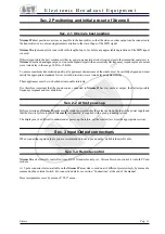
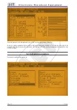
Page 12: ...p To align Xtreme II with your system as the first operation we advise you to recall one of the configurations preset inside Xtreme II Starting from the initial menu Home press Jog and enter the menu Process By pressing Jog you can select Recall Preset then choose one of the 18 preset curves ...

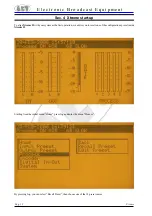
Page 13: ...o use Xtreme II s 2 channel output you must disable the pre enphasis or in any event use the transmitter s linear inputs This measure is essential in all cases even if telephone lines are used up to the transmitter to transfer the signal To enable Xtreme II pre enphasis on the Right and Left outputs carry out the following set up From Home menu press Jog and select Output Preset ...

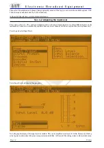
Page 14: ...ce of music CD with good dynamics and a rich sound Adjust the mixer to obtain 0dB indication on the instruments From now on disable any equaliser from any mixer channel with the exception of any microphones only Press Jog and select Input Preset Select Input Level and choose Change option Now the graphic display of the input level is available This can be amplified or reduced of 12 dBu By means of...

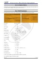
Page 15: ...enerated by Xtreme II Press Jog and select Encoder Below you will find the parameters that may be changed PARAMETER SELECTABLE VALUES Configurazione Left Right LR OFF L OFF R OFF LR ON Mode STEREO MONO Pilot Level OFF 28dB 14 4dB Pilot Phase 15 15 Composite Clipper OFF ON Out 1 Level 0 12dBu Out 2 Config MPX SYNC Out 2 Level 0 12dBu SCA Input 0 14dBu RDS Input 0 14dBu without RDS coder 31 5 17 5dB...

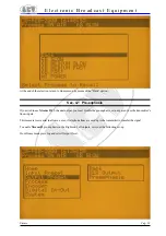
Page 16: ...by means of the Jog If you are varying a parameter but you wish to return to the previously set value a X is shown on the right of the bargraph which not only stresses the control used but it also goes off if the set value corresponds to the parameter value before any change Sec 4 4 System menu options System menu enables following set up ...

Page 17: ...option by mistake by switching the machine off and on no change is carried out To perform Updating see the appropriate description at the end of the manual Here some of the menus which can be seen Sec 4 4 1 Setting date and time To set a new date and time press Jog and enter the System menu Then select Time Date select the value to change and turning the Jog set the new data By pressing Jog again ...

Page 18: ...ols are available PARAMETER SELECTABLE VALUES Brilliance 0 6 dB HF Clipping 0 6 dB Presence 0 6 dB Mid Bass Boost OFF 0 12 dB Low Bass Boost OFF 2MA 12 MA 2MB 12 MB Bass Matching 0 100 30 Hz Filter OFF ON Voice Bass Boost OFF ON Gate Threshold OFF 44 15 dB AGC OFF ON AGC Drive 10 25 dB AGC Release 0 20 dB Sec Multiband Drive 0 25 dB Multiband Release FAST MID FAST MID SLOW SLOW Multiband Clip Driv...

Page 19: ...s At full scale of MODE A there is automatic change over to MODE B MODE B cancels mode A and increases a more muffled softer bass Sec 5 6 BASS MATCHING Used to keep the Bass if Low Bass Boost is set high If low bass amplification is increased too much sometimes the bass tends to go off its limit it does not leave the 75KHz modulation The off limits bass effect is purely an acoustic effect By using...

Page 20: ...ecommend 45dB Sec 5 10 AGC On Off Activates the input pre leveller without which Xtreme could change the timbre according to level Always leave it ON Sec 5 11 AGC Drive For piloting AGC When the machine is aligned with respect to the mixer see installation chapter adjust this control in order to SQUASH the AGC bar to 10 15 dB in the event of a fully modulated programme 0 dB ON MIXER Sec 5 12 AGC R...

Page 21: ...om 0 0 to 1 0 Sec 5 16 Final Clip Drive Control of final sound pressure The sound is more or less amplified to reach a 75KHz maximum deviation 0 0 the original process sound 5 0 an exasperated sound at the limit of the first distortion We recommend from 0 0 to 1 0 max Sec 5 17 Downward Expander The noise ground noise reducer to be activated if using many tape supports or if the sources going on th...

Page 22: ... you can contact the customer service Connect the serial cable between Xtreme II and PC By means of the RS 232 menu select the option XTREME At the end of these presets you can arrange your Xtreme for the updating From now on follow carefully the instructions given by the updating program installed on your PC The non compliance with these instructions may cause Xtreme to block The block can be rem...

Page 23: ...Xtreme Pag 23 E l e c t r o n i c B r o a d c a s t E q u i p m e n t Sec 7 Connection Sec 7 1 Connection PC RS232 Sec 7 2 Sample connection Remote RDS Xtreme II ...

Page 24: ...treme Sez 7 3 Sample connection Remote Sez 7 4 Sample connection Analog AES EBU Sez 7 5 Example of balanced connection for Analog AES EBU I O Sez 7 6 Example of unbalanced connection for Analog I O OUTPUT INPUT 1 GROUND 1 GROUND 2 INPHASE 2 INPHASE 3 RETURN 3 RETURN ...

Page 25: ...put level 16 dBu Connector XLR type female EMI suppressed Pin 1 Chassis Pin 2 3 electronically balanced floating and symmetrical ANALOG AUDIO OUTPUT Configuration Left and Right Flat or pre emphasized 50µS 75µS Impedance 30 Ohm electronically balanced and floating Minimum load impedance 600 Ohm Maximum output level 12 dBu into 600 ohm load Connector XLR type male EMI suppressed Pin 1 Chassis Pin 2...

Page 26: ... and Biphase Modulation DSB suppressed carrier Frequency 57 KHz Bandwith 2 4 KHz RDS output level 0 dBu connector out MPX RDS Connector BNC EMI suppressed DATA SYNCRHONISATION Terminal Interface RS232 at rear asynchronous Data Input Full duplex Format Selectable Transmission Speed 2400 19600 baud Connector 9 contact subminiature cannon female RDS Data management Microprocessor controlled 128 Kbyte...

Page 27: ... Pag 27 E l e c t r o n i c B r o a d c a s t E q u i p m e n t GENERAL SPECIFICATION Power supply 87 265 VAC 50 60 Hz 60 VA Dimensions 19 48 3 cm wide 7 17 8 cm high 15 38 5 cm deep 3 Rack units Weight 12Kg ...

Reviews: