background image

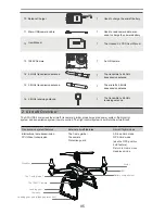
11 Micro-USB camera cable

12


13 1080P Camera

User Manual

An HD camera

The transmitter’s 2.4GHz 

transmission antenna

Used to read camera data; also 

used to charge the camera battery

The Hubsan X4 PRO User Manual

14 2.4GHz transmission antenna

1

The aircraft’s 5.8GHz 

transmission antenna

15 5.8GHz transmission antenna

1

1

1

1

10 Balance Charger

Used to charge the aircraft battery

1

16 5.8GHz receiving antenna

The transmitter’s 5.8GHz 

receiving antenna

1

05


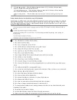
2  Aircraft Overview

Transmission system features 

External aircraft features

Aircraft flight modes

Bidirectional data transmission
FPV/Video transmission

The 1-axis gimbal
The camera
Protection guard

Altitude Hold mode
GPS Hold mode 
(aka the GPS positi

on

Return to Home mo

de

hold feature)

Headless mode

Propeller

Motor

The 1-axis gimbal

The 1080P Camera

Battery compartment

Landing gear

Landing gear pad (slippage prevention)

Compass

LED

The APHUDX4

    comprises the aircraft, its camera, gimbal, propeller guards, power system, flight control 

system and transmission system (remote control). The flight control system is built into the aircraft itself.

Summary of Contents for APHUB X4

Page 1: ...Read the User Manual and its instructions carefully before use 14 User Manual Version 1 0 APHUB X4 REAL TIME FPV Users may download the User Manual from the official AERPRO website WWW AERPRODRONE COM ...

Page 2: ...e impact burn drop or trample the battery Do not short circuit or put the battery terminal in contact with metal Do not expose the battery to temperatures above 60 C Charge the aircraft battery prior to flight Use a Hubsan dedicated charger for charging Keep the battery out of the reach of children and away from any kind of moisture Do not fly the quad in crowded areas and always be aware of the s...

Page 3: ...tting to know the transmitter 5 3 Key functions 02 02 02 04 03 05 06 06 07 07 09 09 12 13 13 14 14 15 15 15 16 17 5 4 Battery installation 5 5 Transmitter stick calibration 5 6 Antennas 5 7 How to set or change the 5 8GHz video frequency 5 8 Binding the transmitter and aircraft Getting Ready to Fly 6 Compass Calibration 6 1 Compass Calibration 6 2 Horizontal Calibration 6 3 Rotational Calibration ...

Page 4: ... adapter 1 A 110 240v adapter 9 Transmitter sunshield Reduces glare from the remote video screen 1 The APHUDX4 is a four rotor quadcopter made for aerial photography and filmography It comes equipped with a high precision single axis gimbal 1080P HD camera and an advanced flight control system The FPV remote control is capable of long range flight while supplying real time video transmission FPV T...

Page 5: ...ntenna 1 05 2 Aircraft Overview Transmission system features External aircraft features Aircraft flight modes Bidirectional data transmission FPV Video transmission The 1 axis gimbal The camera Protection guard Altitude Hold mode GPS Hold mode aka the GPS position Return to Home mode hold feature Headless mode Propeller Motor The 1 axis gimbal The 1080P Camera Battery compartment Landing gear Land...

Page 6: ... C 40 C Ambient temperature for use 20 C 50 C Environmental humidity for charging and use 80 Before flight check that the remote control and aircraft have sufficient power to fly Check the drone fuselage and propellers carefully Broken or failed parts may cause dangerous malfunc tions Check that the battery is securely connected to the aircraft Loose connections may be shaken by intense flight and...

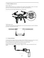
Page 7: ...onnect the battery adapters to power off the aircraft If the drone and transmitter are successfully paired users may view power levels for both the transmitter and drone on the remote control screen 1 Connect the balance charger to the AC power adapter 100 240 V 50 60Hz if necessary use a power conversion plug The balance charger LEDs will flash green indicating th at it is on standby as shown bel...

Page 8: ...ments with high static electricity 64V and above 20 Do not use or charge in temperatures below 0 and above 45 21 If a newly purchased battery is used leaking possesses a bad smell or any other abnormality return immediately to the vendor 22 Keep away from the reach of children 23 Use a dedicated battery charger and follow all charging requirements 24 Minors who use the battery and its dedicated un...

Page 9: ...may then use the transmitter s camera and video function keys to take pictures and record video 1 3 4 5 6 7 8 9 10 11 2 Flight control system components 1 Propeller 2 Motor 3 LED 4 Gimbal shock absorbers 5 The 1 axis gimbal 6 The 1080P Camera 7 Landing gear 8 Compass 9 Battery compartment 10 Gimbal and battery interface 11 Landing gear pad slippage prevention The motherboard Also known as the mind...

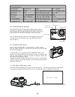
Page 10: ...n Video botton Recording button Camera lens LED Indicator Microphone USB Note The H906A transmitter is also used for photography video recording and playback For more information refer to the H906A key functions section on page 17 Before using the APHUDX4 to take pictures or videos please insert the Micro SD card into the card slot as shown on the right when the camera is turned off A Micro SD is ...

Page 11: ...also charge if it is connected to the aircraft Camera status indicator Camera status Solid blue no red Camera is on standby mode Solid blue with a red light flashing every second Camera is recording video Camera has encountered a failure or malfunction Solid blue and solid red Blue light no red flashing every second Micro SD is full no card sensed in the camera there is a problem with the Micro SD...

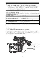
Page 12: ...m a c d n a l a b m i g e h t o t e n i l n o i s s i m s n a r t l a n g i s s l a b m i g e h t g u l P 2 below s a e l b a c n o i s s i m s n a r t l a n g i s s l a b m i g e h t f o t f e l e h t o t e l b a c n o i s s i m s n a r t V P F s a r e m a c e h t g u l P 3 shown in the figure below The gimbal signal line should be inserted with brown wire matching the negative polarity If the gi...

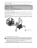
Page 13: ...zes the direction in which the propeller is tightened Unlock symbolizes the direction which the propeller is loosened 3 2 Installation 1 Before installing the propellers please check to make sure that all letters on the propellers match the letters on the motor arms Propeller A s go with A motors and propellers B s go with B motors 2 Mount all 4 propellers on their motors A to A motors Bto Bmotors...

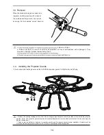
Page 14: ...ck that all propellers are free of deformations and undamaged If any propeller is damaged please replace before flying performance Remove the existing fuselage screws first Use the longer propeller guard screws provided to then install the propeller guards Note The propeller guard screws and assembly disassembly tools needed are located in the box housing the guards themselves Please note the dist...

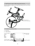
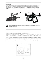
Page 15: ... A i r c r a f t i n L e v e l C a l i b r a t e C o m p a s s 1 7 3V 2 Aircraft Power Voltage Heading Roll Pitch Speed Distance Altitude Aircraft GPS Satellites Remote Control GPS Satellites GPS coordinates Remote control power voltage Remove the antenna from its wrappings and locate the gold SMA connector at the side of the unit Attach the antenna to the connector by screwing it on clockwise Aft...

Page 16: ...hrottle Trim 1 Throttle Aileron stick 3 Aileron Trim ENT Function Key Down Function MODE 2 7 Power SW 6 Throttle Trim 1 Throttle Rudder Stick 5 Rudder Trim UP Function EXT Function Key LCD SA GPS 5 8GHz Antenna 9 Antenna 8 Neck Strap Eyelet 4 Elevator Trim 2 Elevator Aileron stick 3 Aileron Trim ENT Function Key Down Function T1 T2 Home SB SA GPS T1 T2 Home SB Video glasses socket USB Socket ...

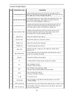
Page 17: ...ases the tension of your hands from holding the transmitter 9 10 13 14 Antenna SA Transmits the 2 4Ghz wireless signal Push Headless Function Pull down Normal Function 11 T2 No function for now 12 GPS Push Altitude mode and Position Mode Pull down Exit the Altitude Mode and Position Mode Home T1 SB Push Enter the RTH function Pull down Exit the RTH function 15 16 17 USB Socket Only for engineer to...

Page 18: ...upper right corner Power the transmitter on while holding both sticks in their respective positions the LCD screen will show Calibrate Sticks Mode 2 Let go of the sticks then pull them up down towards the center and outwards Repeat this sequence 3 times then release both sticks and hold the Exit key until the transmitter beeps This indicates a successful calibration Mode 2 Push both sticks to the ...

Page 19: ...better video transmission signal To adjust the 5 8GHz frequency first pull and hold the throttle stick downwards to the very bottom of its socket While doing so long press the Enter key to enter the Main Menu Use the Up Down keys and scroll to the 5 8G frequence selection Press Enter to enter the frequency menu use the Up and Down keys to browse the different frequencies Long press the Exit key fo...

Page 20: ...high pressure lines airports or areas with severe magnetic interference 1 Make sure the aircraft battery and mobile device are charged and have adequate power 2 Confirm that propellers are properly installed 3 Check that the gimbal is properly installed and that all lines are inserted into the correct sockets 4 If one is taking pictures insert the Micro SD card required for taking pictures and vid...

Page 21: ...aircraft is powered on its compass will automatically test for deviations in the local magnetic field If deviations are detected the aircraft will automatically enter compass calibration mode The remote control screen will first read Calib compass 1 and the LEDs should be red flashing clockwise Slowly rotate the aircraft on the horizontal plane until the aircraft LEDs change color The remote contr...

Page 22: ...ven tilted surface or there will be errors If the aircraft drifts while rotating in flight perform a rotation calibration Hold the left stick up to the top of its socket Rapidly and continuously wiggle the right stick up and down until all 4 LEDs flash slowly Make sure that the quad is on a completely flat and smooth surface place a small piece of paper under each foot When all the 4 LED indicator...

Page 23: ...e throttle up and the aircraft ascends Pull the throttle back and the aircraft descends When the joystick is centered unmoving the aircraft will hold its altitude in the air The throttle must be pushed upwards beyond center point for the aircraft to completely takeoff from the ground The harder the throttle is pushed the faster the aircraft will ascend Please push the throttle slowly for a gradual...

Page 24: ...e degree of the aircraft s tilt and therefore the velocity of its forward and backward movement The harder the elevator is pushed the greater the aircraft s tilt angle and flight speed either forwards or backwards The aileron controls the aircraft s left and right movement Push the joystick to the left and the aircraft will tilt and fly leftwards Pull the joystick to the right and the aircraft wil...

Page 25: ...2V If you would like to reverse any of the stick functions please follow the instructions below Be aware that this will reverse the control commands Pull the throttle stick down to the lowest position and long press the Enter key to open the Main Menu interface Use the Up Down keys to select Set reverse and use the Enter key to switch between modes Long press Exit key to save and exit If you would...

Page 26: ...26 E g Re e e F p e RT s ex Re e e L e 5 R 4 ...

Page 27: ...f point When the aircraft and transmitter have gained 6 or more satellites in GPS Hold mode the failsafe home point will be recorded as the takeoff point 1 Transmitter is powered off 2 The flight distance exceeds the remote control s signal transmission range 3 There is an obstacle between the remote control and aircraft 4 The flight control or transmitter signal is interrupted by strong external ...

Page 28: ...s then release both sticks and hold the Exit key until the transmitter beeps This indicates a successful calibration Mode 2 Push both sticks to the upper left corners Power the transmitter on while holding both sticks in their respective positions the LCD screen will show Calibrate Sticks Mode 2 Let go of the sticks then pull them up down towards the center and outwards Repeat this sequence 3 time...

Page 29: ...mitter Make sure that the gimbal line is properly connected to the aircraft especially after a crash Always check the state of the aircraft and its components after any kind of crash If you need assistance setting up or using your Aerpro product now or in the future call or email Aerpro Support Australia and International inquires NOTE Maintaining control of the drone while flying is the sole resp...

Page 30: ...ra Real Time FPV Photo Video Stable 1 Axis Gimbal System FPV1 Transmitter Flight time around 20 25 minutes 11 1V 7000mAH Li Po battery Low voltage battery protection Automatic return switch Failsafe to return home landing GPS Positioning GPS RTH Auto pilot function GPS and altitude modes provide stability N S E W 1080P Features Specifications ...

Page 31: ...where there are people Fly the aircraft in daylight only Give way to all other aircraft You don t want your aircraft destroyed in a collision with a bigger aircraft or be responsible for damaging it or for putting people s lives at risk You cannot fly your aircraft higher than 120 metres 400 feet above ground level You cannot fly closer than 5 5 kilometres from an airfield You cannot fly in controlle...

Page 32: ...d to other aircraft property and people That means not flying it over areas where there are people Fly the aircraft in daylight only Give way to all other aircraft You don t want your aircraft destroyed in a collision with a bigger aircraft or be responsible for damaging it or for putting people s lives at risk You cannot fly your aircraft higher than 120 metres 400 feet above ground level You canno...

Reviews: