Installation, Operation & Maintenance Manual
IM-502
22
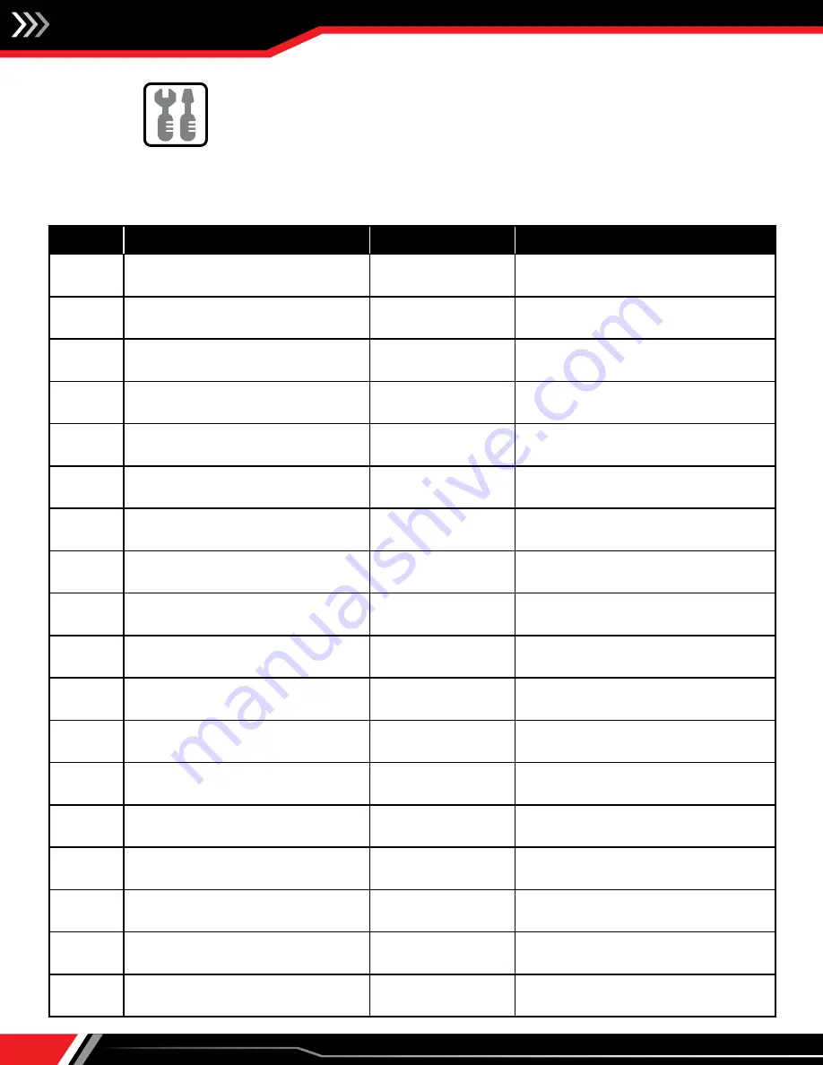
Date
Completed Maintenance
Performed By
Comments
Model Number __________________________
Serial Number __________________________
Fan Maintenance Log
Page 1: ...here are general in nature Additional product and engineering information is available at www tcf com Table of Contents Exploded View 2 Fan Overview Impeller Rotation and Airflow 3 Fan Nameplate 3 Dim...
Page 2: ...ng Bird Screen Impeller Shroud Curb Cap Vent Tube Drain Support Brackets Horizontal Support Post Vertical Support Post Upblast Exhaust Fan Models PCU PCUB Downblast Exhaust Fan Model PC Motor Cover Mo...
Page 3: ...0 10 5 43 dimensional data Model PC Downblast Fan Overview Precisely designed for use in roof and wall exhaust applications the fans covered in this manual offer a broad range of end use applications...
Page 4: ...es that are hot the fan housing could be hot Sharp edges wear protective gloves when handling installing or servicing a fan Fans can operate at high decibel sound levels Wear proper ear protection to...
Page 5: ...PCU fans All Sizes Fans may be lifted using hooks around the four 4 horizontal support posts with a minimum of four lifting straps with spreader bars to ensure that no contact is made with the motor h...
Page 6: ...dance with the bearing manufacturer s instructions The drives and belts should be removed if the fan is to be stored for a prolonged period The drives should be labeled for service and stored in a dry...
Page 7: ...ion for details 3 Perform fan pre check See Check Test Start Procedure section for a full checklist 4 Perform installation of any externally mounted accessories that were shipped loose with the fan 5...
Page 8: ...e idler pulley along the groove to either tighten or loosen the belt See image to the right c Verify the RPM of the impeller Adjustment can be made via the variable speed sheave attached to the motor...
Page 9: ...es are required it may be necessary to increase wire size to prevent excessive voltage drop Wires should be sized for a maximum of 3 voltage drop 4 Disconnect switches are not fused The power leads mu...
Page 10: ...ions The standard pillow block bearings on belt driven ventilators are factory lubricated and are provided with external grease fittings Annual lubrication is recommended or more frequently if needed...
Page 11: ...tor and line voltage 115V only Never connect across line See Connection Diagrams Minimum Speed Setpoint All controls are factory set to 65V 3V output as standard with an input voltage of 120V If diffe...
Page 12: ...mes necessary to adjust belt tension do not over tension as bearing damage will occur Recommended belt tension should permit 1 64 deflection per inch of span of the belt at the center of the belt span...
Page 13: ...or three months is suggested 3 All motors supplied with Aerovent ventilators carry a one year limited warranty from date of shipment For repairs within the warranty period the motor must be taken to t...
Page 14: ...les on the curb hinge to the holes on the curb cap This should be on the opposite side of the drain A B Step 2 Insert provided screws to affix the hinge to the curb cap Step 3 Place and install fan on...
Page 15: ...Nut Hex 4 Security Hasp Hinged Step 1 Drill 4 0 19 holes on center curb cap from either corner Step 2 Attach the hasp to the curb cap by using the included 10 hardware Step 3 Drill 4 0 19 holes on ce...
Page 16: ...corner of curb base Step 2 Attach chain to outside of curb base with bolt head on inside of curb base Step 3 Use one flat washer under bolt head and one on top of chain Step 4 Use remaining fasteners...
Page 17: ...ping screws that are fastened to the support post Step 2 Drill holes and install firestat Holes must be near a support post Note The hole drilled in the motor housing must be close to in line with the...
Page 18: ...on Step 1 Place the insect screen between the fan inlet and the roof or roof curb Fasten with screws or nails if desired Performance Baffle Installation Step 1 Place the performance baffle between the...
Page 19: ...1 Attach using sheet metal screws Roof curbs come with damper trays Grease Box Installation Step 1 Fasten the grease box to the curb cap under the drain using supplied hardware Parts Included Grease...
Page 20: ...y airstream can generate noise 4 Poor fan inlet conditions 5 Acoustics or sound measurement procedure incorrect Vibration Problems 1 Poor foundation or mounting structure resonances 2 Foreign material...
Page 21: ...tial Fan Check Inspect fan for damage Are the bolts tight Fan Impeller Impeller overlap checked Fasteners tight Impeller rotates freely Bearings Bearings aligned Bearings greased Note Rotate while gre...
Page 22: ...nstallation Operation Maintenance Manual IM 502 22 Date Completed Maintenance Performed By Comments Model Number __________________________ Serial Number __________________________ Fan Maintenance Log...
Page 23: ...nstallation Operation Maintenance Manual IM 502 23 Date Completed Maintenance Performed By Comments Model Number __________________________ Serial Number __________________________ Fan Maintenance Log...
Page 24: ...WWW AEROVENT COM 5959 Trenton Lane N Minneapolis MN 55442 Phone 763 551 7500 Fax 763 551 7501 2022 Aerovent...