Electrical Specifications and Installation
PRO225LM Hardware Manual
3.1. Motor and Feedback Connectors
Stages equipped with standard motors and encoders come from the factory completely wired and
assembled.
N O T E :
Refer to the other documentation accompanying your Aerotech equipment. Call your Aerotech
representative if there are any questions on system configuration.
N O T E :
If using standard Aerotech motors and cables, motor and encoder connection adjustments are
not required.
The PRO225LM's protective ground connection provides motor frame ground protection only. Additional
grounding and safety safeguards are required for applications requiring access to the stage while it is
energized. The System Integrator or qualified installer is responsible for determining and meeting all safety
and compliance requirements necessary for the integration of this stage into the final application.
D A N G E R : Remove power before connecting or disconnecting electrical components or
cables. Failure to do so may cause electric shock.
W A R N I N G : The protective ground connection must be properly installed to minimize the
possibility of electric shock.
W A R N I N G :
For stages with the -CMS0 option:
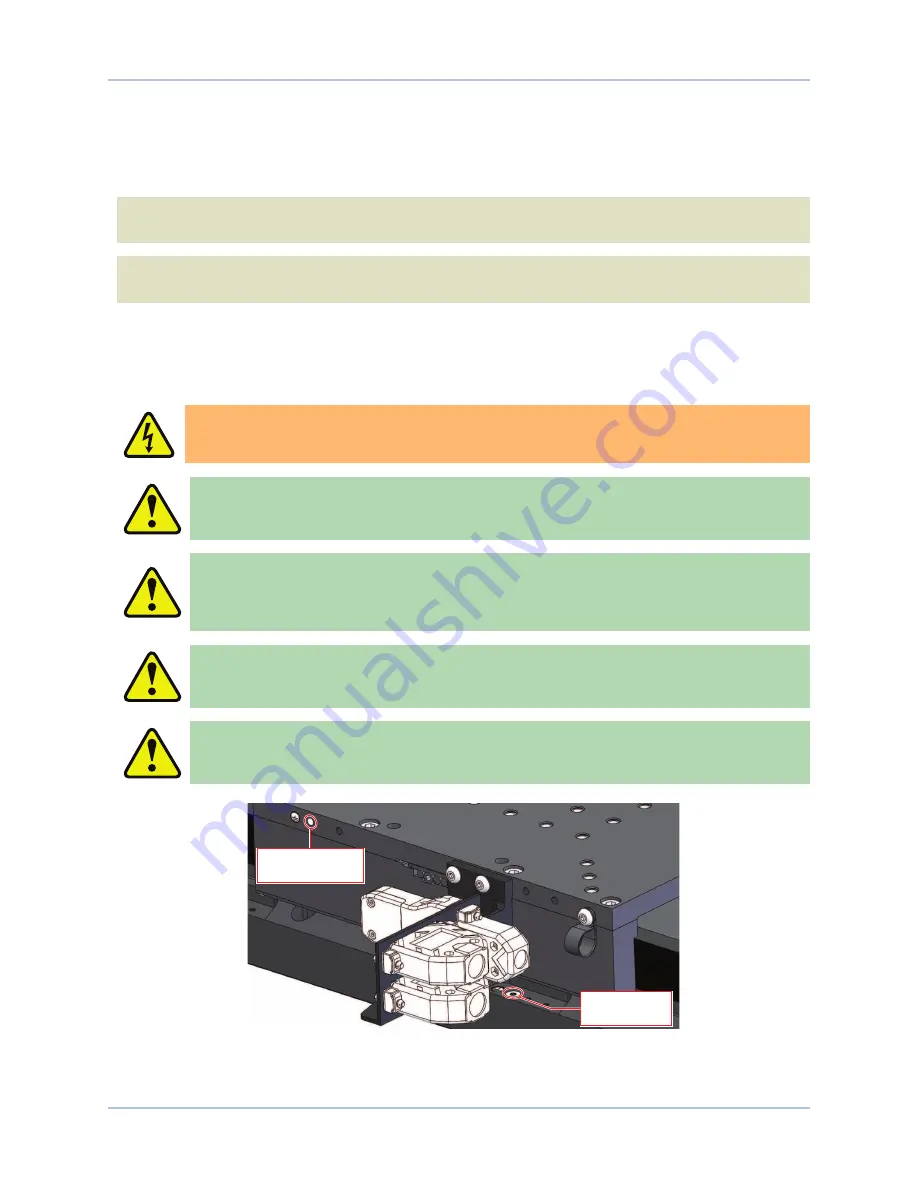
Ground wire connection points are
provided at the tabletop and stage base. A user-supplied ground wire is recommended and may
be useful in the final application to reduce noise or provide additional grounding for customer
supplied equipment. Refer to
for ground connection points.
W A R N I N G : Operator access to the base and tabletop must be restricted while connected
to a power source. Failure to do so may cause electric shock.
C A U T I O N : The stage controller must provide over-current and over-speed protection.
Failure to do so may result in permanent damage to the motor and stage components.
Base Ground
Connection
Tabletop Ground
Connection
Figure 3-1:
Ground Connection Points for the -CMS0 Option
28
Chapter 3
www.aerotech.com


