background image

ARMS Hardware Manual

Revision History

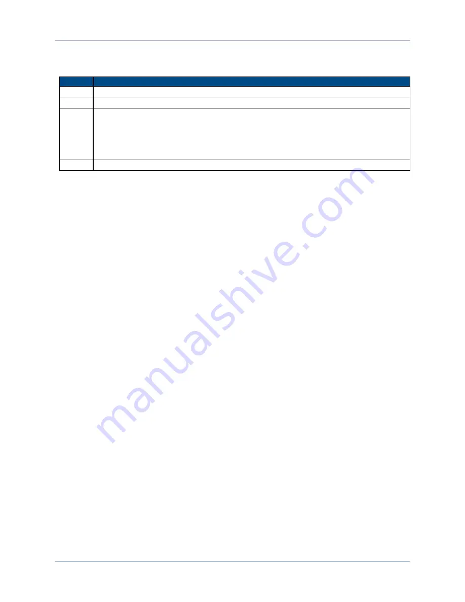
Appendix B: Revision History

Revision

General Information

1.03.00

Complete manual revision

1.02.00

Changed motor feedback pin 8 to reserved

1.01.00

l

Declaration of Incorporation added

l

Environmental Specifications added

l

Safety information and warnings added/updated

l

Motor Specifications added

l

Note about wire current and voltage requirements added

1.00.00

New manual

www.aerotech.com

Appendix B

45

Summary of Contents for ARMS Series

Page 1: ...Revision 1 03 00 ARMS Series Stage Hardware Manual...

Page 2: ...vice aerotech com 101 Zeta Drive Pittsburgh PA 15238 2811 www aerotech com United Kingdom Japan Phone 44 0 1256 855055 Fax 44 0 1256 855649 Email service aerotech co uk Phone 81 0 50 5830 6814 Fax 81...

Page 3: ...ion 15 2 1 Unpacking and Handling the Stage 15 2 2 Dimensions 16 2 3 Securing the Stage to the Mounting Surface 25 2 4 Attaching the Payload to the Stage 27 Chapter 3 Electrical Specifications and Ins...

Page 4: ...destal Dimensions for the ARMS200 HDP 21 Figure 2 7 ARMS260 Dimensions TT1 TT2 TT3 TT4 22 Figure 2 8 ARMS260 Dimensions TT5 TT6 TT7 TT8 23 Figure 2 9 Mounting Pedestal Dimensions for the ARMS260 HDP 2...

Page 5: ...5 ARMS260 Series Specifications 13 Table 2 1 Stage to Mounting Surface Hardware 25 Table 3 1 Motor Wiring Connector 30 Table 3 2 Feedback Connector 31 Table 3 3 Feedback Specifications 33 Table 3 4 S...

Page 6: ...the possibility of electrical shock bodily injury or death the following precautions must be followed 1 Moving parts can cause crushing or shearing injuries Access to all stage and motor parts must b...

Page 7: ...er more declares that it is not allowed to put the equipment into service until the machinery into which it is to be incorporated or of which it is to be a component has been found and declared to be...

Page 8: ...Table of Contents ARMS Hardware Manual 8 www aerotech com This page intentionally left blank...

Page 9: ...and ARMS200 only SR02 1 24 lines 2A max current SR03 1 3 36 lines 2A max current ARMS200 only SR04 1 48 lines 2A max current ARMS260 only SR05 1 3 56 lines 2A max current ARMS200 only SR06 1 72 lines...

Page 10: ...otech if your specific application involves use above 2 000 m or below sea level Vibration Use the system in a low vibration environment Excessive floor or acoustical vibration can affect system perfo...

Page 11: ...000 s2 Inertia unloaded 7 6 600 kg mm2 9 700 kg mm2 Total Mass 7 9 kg 15 kg Servo Bandwidth 8 70 Hz 3 dB Material Aluminum Stage Finish Black Anodize Tabletop Finish Hard Coating 62 Rockwell Hardness...

Page 12: ...Tabletop Finish Hard Coating 62 Rockwell Hardness 1 Height may vary with certain slip ring and rotary union options refer to for more details 2 Aperture not available with allslip ring and rotary uni...

Page 13: ...e Tabletop Finish Hard Coating 62 Rockwell Hardness 1 Height may vary with certain slip ring and rotary union options refer to for more details 2 Aperture not available with allslip ring and rotary un...

Page 14: ...Overview ARMS Hardware Manual 1 4 Vacuum Operation Contact the factory for information regarding operation in a vacuum environment 14 Chapter 1 www aerotech com...

Page 15: ...ffect the performance of the ARMS Use care when moving the ARMS Carefully remove the ARMS from its protective shipping container Gently set the ARMS on a smooth flat and clean surface Before operating...

Page 16: ...Installation ARMS Hardware Manual 2 2 Dimensions Figure 2 1 ARMS150 Dimensions TT1 TT2 TT3 TT4 16 Chapter 2 www aerotech com...

Page 17: ...ARMS Hardware Manual Installation Figure 2 2 ARMS150 Dimensions TT5 TT6 TT7 TT8 www aerotech com Chapter 2 17...

Page 18: ...Installation ARMS Hardware Manual Figure 2 3 Mounting Pedestal Dimensions for the ARMS150 HDP 18 Chapter 2 www aerotech com...

Page 19: ...ARMS Hardware Manual Installation Figure 2 4 ARMS200 Dimensions TT1 TT2 TT3 TT4 www aerotech com Chapter 2 19...

Page 20: ...Installation ARMS Hardware Manual Figure 2 5 ARMS200 Dimensions TT5 TT6 TT7 TT8 20 Chapter 2 www aerotech com...

Page 21: ...ARMS Hardware Manual Installation Figure 2 6 Mounting Pedestal Dimensions for the ARMS200 HDP www aerotech com Chapter 2 21...

Page 22: ...Installation ARMS Hardware Manual Figure 2 7 ARMS260 Dimensions TT1 TT2 TT3 TT4 22 Chapter 2 www aerotech com...

Page 23: ...ARMS Hardware Manual Installation Figure 2 8 ARMS260 Dimensions TT5 TT6 TT7 TT8 www aerotech com Chapter 2 23...

Page 24: ...Installation ARMS Hardware Manual Figure 2 9 Mounting Pedestal Dimensions for the ARMS260 HDP 24 Chapter 2 www aerotech com...

Page 25: ...factory If machining is required to achieve the desired flatness it should be performed on the mounting surface rather than the ARMS Shimming should be avoided if possible If shimming is required it...

Page 26: ...ation ARMS Hardware Manual Counterbored Mounting Holes QTY 4 Side Mount Holes QTY 4 per side on 3 sides Figure 2 10 Standard Mounting Holes Figure 2 11 Side Mount Mounting Holes 26 Chapter 2 www aerot...

Page 27: ...vo instability can occur Refer to the controller help file for tuning assistance The payload must be flat rigid and comparable to the stage in quality to maintain optimum performance N OTE For valid s...

Page 28: ...Installation ARMS Hardware Manual Figure 2 13 ARMS Cantilevered Load Capability 28 Chapter 2 www aerotech com...

Page 29: ...e appropriate connections If system level integration was purchased an electrical drawing showing system interconnects has been supplied with the system separate from this documentation The electrical...

Page 30: ...safety and compliance requirements necessary for the integration of this stage into the final application W A R N I N G The protective ground connection must be properly installed to minimize the poss...

Page 31: ...6 Marker N 7 Marker 8 Reserved 9 Reserved 10 Hall Effect sensor phase A 11 Hall Effect sensor phase C 12 Reserved 13 Reserved 14 Cosine 15 Cosine N 16 5 V power supply 17 Sine 18 Sine N 19 Reserved 2...

Page 32: ...ting Specifications ARMS Hardware Manual 3 2 Motor and Feedback Wiring Shielded cables are required for the motor and feedback connections Figure 3 1 Motor and Feedback Wiring 32 Chapter 3 www aerotec...

Page 33: ...V max pull up Output Current 5 mA sinking Thermistor Specifications Polarity Logic 0 no fault Logic 1 over temperature fault Cold Resistance 100 Hot Resistance 10 K Note 1K pull up to 5V recommended...

Page 34: ...ce C W 0 95 0 64 Number of Poles 18 18 1 Performance is dependent upon heat sink configuration system cooling conditions and ambient temperature 2 Values shown 75 C rise above a 25 C ambient temperatu...

Page 35: ...stance C W 0 67 0 57 Number of Poles 18 18 1 Performance is dependent upon heat sink configuration system cooling conditions and ambient temperature 2 Values shown 75 C rise above a 25 C ambient tempe...

Page 36: ...ent temperature 2 Values shown 75 C rise above a 25 C ambient temperature with housed motor mounted to a 330 mm x 330 mm x 13 mm aluminum heat sink 3 Peak force assumes correct rms current consult Aer...

Page 37: ...hasing of the feedback and motor signals and is dictated by the stage wiring refer to Section 3 5 for Motor and Feedback phasing information Programming direction of a stage is set by the controller t...

Page 38: ...erating Specifications ARMS Hardware Manual 3 5 Motor and Feedback Phasing Motor phase voltage is measured relative to the virtual wye common point Figure 3 3 Hall Phasing 38 Chapter 3 www aerotech co...

Page 39: ...ARMS Hardware Manual Operating Specifications Figure 3 4 Analog Encoder Phasing Reference Diagram www aerotech com Chapter 3 39...

Page 40: ...Operating Specifications ARMS Hardware Manual 40 Chapter 3 www aerotech com This page intentionally left blank...

Page 41: ...ect and perform an operational check on all safeguards and protective devices In general repair and or replacement of damaged or malfunctioning components by Aerotech field service personnel is not po...

Page 42: ...lt See controller documentation Stage moves uncontrollably Encoder sine and cosine signals connections See Chapter 3 and Controller documentation Motor Connections See Chapter 3 and Controller documen...

Page 43: ...ch approval A Return Materials Authorization RMA number must accompany any returned product s The RMA number may be obtained by calling an Aerotech service center or by submitting the appropriate requ...

Page 44: ...and conditions stated in the following On Site Non Warranty Repair section apply On site Non Warranty Repair If any Aerotech product cannot be made functional by telephone assistance or purchased repl...

Page 45: ...vision 1 02 00 Changed motor feedback pin 8 to reserved 1 01 00 l Declaration of Incorporation added l Environmental Specifications added l Safety information and warnings added updated l Motor Specif...

Page 46: ...Revision History ARMS Hardware Manual 46 Appendix B www aerotech com This page intentionally left blank...

Page 47: ...ons 33 Humidity 10 I Inspection Schedule 41 L label 15 lubrication 41 Lubrication 41 M mounting surface cleaning 25 securing stage 25 P part number 15 Performance Specifications S 130 34 S 180 35 S 24...

Page 48: ...Index ARMS Hardware Manual Support 2 T Technical Support 2 Thermistor Specifications 33 V Vacuum Operation 14 Vibration 10 W Warranty and Field Service 43 48 Index www aerotech com...

Reviews: