ABL1000 Hardware Manual
Electrical Specifications and Installation
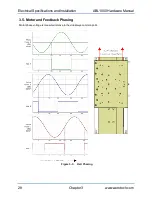
3.3. Motor and Feedback Specifications
Table 3-2:
Feedback Specifications
Hall-Effect Sensors Specifications
Supply Voltage
5 V ±5%
(1)
Supply Current
50 mA
Output Type
Open Collector
Output Voltage
24 V max (pull up)
Output Current
5 mA (sinking)
Encoder Specifications
Supply Voltage
5 V ±5%
(1)
Supply Current
<130 mA for E1; <165 mA for E2
Output Signals
Sinusoidal Type (Incremental Encoder)
: 1 V
pk-pk
into 120 Ω Load (differential
signals SIN+, SIN-, COS+, COS- are .5 V
pk-pk
relative to ground.)
Limit Switch Specifications
Supply Voltage
5 V ±5%
(1)
Supply Current
25 mA (typical)
Output Type
Open Collector
Output Voltage
5 V
Output Current
10 mA max (sinking)
Output Polarity
Normally Closed (NC)
l
Sinks current to ground (Logic "0") when not in limit
l
High impedance (Logic "1") when in limit
l
Requires external pull-up to +5 V (10 kΩ recommended)
1. Halls, encoder, and limits are interconnected to a common 5VDC supply (see
).
Note:
If the ABL1000 is driven beyond the electrical limit, it will encounter a mechanical stop. Impacting the mechanical stop could
cause damage to the stage even at low speeds.
Table 3-3:
Encoder Specifications
Model
Fundamental Signal Period
Digital Resolution
-E1
20 µm
--
-E1 with x4000 Interpolation
5 nm
-E1 with x16000 Interpolation
1.25 nm
-E2
4 µm
--
-E2 with x4000 Interpolation
1 nm
-E2 with x16000 Interpolation
0.25 nm
NOTE:
Quadrature decoding included in interpolated resolution calculations
www.aerotech.com
Chapter 3
25

