background image

Overview

ABL1000 Hardware Manual

1.4. Air Requirements

The quality of the air that you supply to the stage is important to the operation of the stage. Aerotech
recommends that you connect the air supply to the air inlet with a polyurethane air hose.

Table 1-4:

Air Specifications

Description

Air Quality

Nitrogen

(1)

l

99.99% pure

l

filtered

(2)

to 0.25 microns

Compressed Air

l

filtered

(2)

to 0.25 microns

l

dry to 0º F dew point

l

oil free

Operating Air Pressure

80 psi ± 5 psi (517 to 551 kPa)

Air Consumption

17.5 SLPM

Air Inlet Fitting

(3)

1/16" ID x 1/8" OD x 18.75 ft length hose

(1) Recommended
(2) The filtration requirement is to prevent particles from clogging the air bearing openings.
(3) Aerotech recommends using a polyurethane air hose.

Aerotech also recommends that you install a pressure switch (P/N: MCA03094) tied to the motion
controller's emergency stop (ESTOP) that will remove power to the air bearing if pressure drops below 40 psi
(a drop in pressure could result in contact between bearing surfaces which could cause damage to the
surfaces). For easier air-supply setup, you can purchase pneumatic kits and filter/filter-dryer kits from
Aerotech. Aerotech’s ABF Air Filtration Unit incorporates air filtration plus a pressure monitoring switch.

14

Chapter 1

www.aerotech.com

Summary of Contents for ABL1000

Page 1: ...Revision 1 03 00 ABL1000 Hardware Manual...

Page 2: ...967 6870 101 Zeta Drive Pittsburgh PA 15238 2811 www aerotech com United Kingdom Japan Email Support aerotech com Phone 44 0 1256 855055 Fax 44 0 1256 855649 Email Support aerotech com Phone 81 0 50 5...

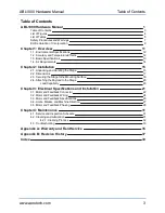
Page 3: ...15 2 2 Dimensions 17 2 3 Securing the Stage to the Mounting Surface 18 2 4 Attaching the Payload to the Stage 20 Load Capability 20 Chapter 3 Electrical Specifications and Installation 21 3 1 Motor a...

Page 4: ...s 19 Figure 2 4 Payload and Multi Axis Stage Mounting Holes 20 Figure 3 1 Motor and Feedback Wiring 24 Figure 3 2 Machine Direction 27 Figure 3 3 Hall Phasing 28 Figure 3 4 Analog Encoder Phasing Refe...

Page 5: ...onmental Specifications 12 Table 1 3 ABL1000 Series Specifications 13 Table 1 4 Air Specifications 14 Table 3 1 Motor and Feedback Connector 23 Table 3 2 Feedback Specifications 25 Table 3 3 Encoder S...

Page 6: ...Table of Contents ABL1000 Hardware Manual 6 www aerotech com This page intentionally left blank...

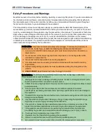
Page 7: ...connected to a power source 3 Disconnect electrical power before servicing equipment 4 All components must be properly grounded in accordance with local electrical safety requirements 5 Operator safe...

Page 8: ...Safety ABL1000 Hardware Manual 8 www aerotech com This page intentionally left blank...

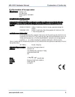
Page 9: ...more declares that it is not allowed to put the equipment into service until the machinery into which it is to be incorporated or of which it is to be a component has been found and declared to be in...

Page 10: ...Declaration of Conformity ABL1000 Hardware Manual 10 www aerotech com This page intentionally left blank...

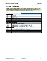
Page 11: ...vel 100 100 mm travel Feedback Required E1 Incremental linear encoder 1 Vpp amplified sine output E2 High accuracy Incremental linear encoder 1 Vpp amplified sine output Cable Management Optional CMS1...

Page 12: ...es use above 2 000 m or below sea level Vibration Use the system in a low vibration environment Excessive floor or acoustical vibration can affect system performance Contact Aerotech for information r...

Page 13: ...tion 6 7 17 5 SLPM Construction Aluminum Body Hardcoat 1 Maximum speed based on stage capability maximum application velocity may be limited by system data rate and system resolution 2 Max load for XY...

Page 14: ...ID x 1 8 OD x 18 75 ft length hose 1 Recommended 2 The filtration requirement is to prevent particles from clogging the air bearing openings 3 Aerotech recommends using a polyurethane air hose Aerote...

Page 15: ...t to let it stabilize at room temperature for at least 12 hours Allowing it to stabilize to room temperature will ensure that all of the alignments preloads and tolerances are the same as they were wh...

Page 16: ...llation ABL1000 Hardware Manual Figure 2 1 Shipping Clamps N OTE After removing the shipping brackets retain them for future use Do not transport or ship the ABL1000 without the shipping brackets atta...

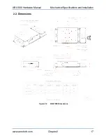
Page 17: ...ABL1000 Hardware Manual Mechanical Specifications and Installation 2 2 Dimensions Figure 2 2 ABL1000 Dimensions www aerotech com Chapter 2 17...

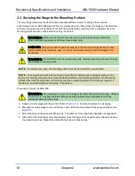
Page 18: ...must be flat to within 1 m per 50 mm N OTE The stage base is precision machined and verified for flatness prior to stage assembly at the factory If machining is required to achieve the desired flatne...

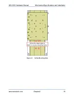
Page 19: ...ABL1000 Hardware Manual Mechanical Specifications and Installation Figure 2 3 Surface Mounting Holes www aerotech com Chapter 2 19...

Page 20: ...as purchased with Aerotech controls it might have been tuned with a representative payload based on the information provided at the time of order If the ABL1000 is started up without a payload the ser...

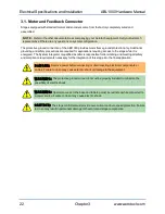
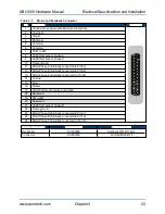
Page 21: ...the motor and encoder are integrated at the factory Refer to the sections that follow for standard motor wiring and connector pinouts The stage and its carriage are protected from dangerous faults by...

Page 22: ...or qualified installer is responsible for determining and meeting all safety and compliance requirements necessary for the integration of this stage into the final application D A N G E R Remove power...

Page 23: ...cted to Pin 23 12 Motor Phase B internally connected to Pin 24 13 Motor Phase C internally connected to Pin 25 14 Cosine 15 Sine 16 Marker 17 5VDC Encoder Halls and Limits 18 Reserved 19 CW LMT 20 Res...

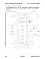
Page 24: ...ring All motor and controller manufacturers have their own designations for motor phases A B C and Hall signals A B C refer to Section 3 5 for motor phasing Shielded cables are required for the motor...

Page 25: ...lector Output Voltage 5 V Output Current 10 mA max sinking Output Polarity Normally Closed NC l Sinks current to ground Logic 0 when not in limit l High impedance Logic 1 when in limit l Requires exte...

Page 26: ...7 Resistance 25 C line line 5 2 Inductance line line mH 0 7 Thermal Resistance No Forced Cooling C W 2 22 Maximum Bus Voltage 7 VDC 80 Magnetic Pole Pitch mm in 16 0 0 63 1 Performance is dependent up...

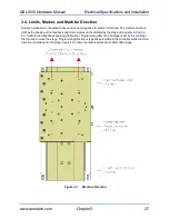
Page 27: ...ack and motor signals and is dictated by the stage wiring refer to Section 3 5 for Motor and Feedback phasing information Programming direction of a stage is set by the controller that is used to move...

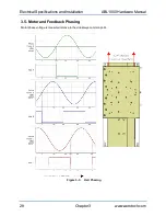
Page 28: ...pecifications and Installation ABL1000 Hardware Manual 3 5 Motor and Feedback Phasing Motor phase voltage is measured relative to the virtual wye common point Figure 3 3 Hall Phasing 28 Chapter 3 www...

Page 29: ...BL1000 Hardware Manual Electrical Specifications and Installation Figure 3 4 Analog Encoder Phasing Reference Diagram Figure 3 5 Encoder Phasing Reference Diagram Standard www aerotech com Chapter 3 2...

Page 30: ...Electrical Specifications and Installation ABL1000 Hardware Manual 30 Chapter 3 www aerotech com This page intentionally left blank...

Page 31: ...ent Monthly inspections should include but not be limited to l Visually inspect the stage and cables l Re tighten loose connectors l Replace or repair damaged cables l Clean the ABL1000 and any compon...

Page 32: ...nd of travel and remove power D A N G E R To minimize the possibility of bodily injury or death disconnect all electrical power prior to performing any maintenance or making adjustments to the equipme...

Page 33: ...ult The system is configured to operate with an air pressure safety switch and either the air pressure is too low or the switch is not present Check the air supply and the switch Air pressure switches...

Page 34: ...Maintenance ABL1000 Hardware Manual 34 Chapter 4 www aerotech com This page intentionally left blank...

Page 35: ...such approval A Return Materials Authorization RMA number must accompany any returned product s The RMA number may be obtained by calling an Aerotech service center or by submitting the appropriate re...

Page 36: ...s and conditions stated in the following On Site Non Warranty Repair section apply On site Non Warranty Repair If any Aerotech product cannot be made functional by telephone assistance or purchased re...

Page 37: ...Added EU Declaration of Incorporation l Added Environmental Specifications Section 1 1 l Updated air flow requirements Section 1 4 l Updated stage specifications Section 1 3 l Added motor specificatio...

Page 38: ...Revision History ABL1000 Hardware Manual 38 Appendix B www aerotech com This page intentionally left blank...

Page 39: ...e air 14 Humidity 12 I Inspection Schedule 31 Isopropyl Alcohol 31 L label 15 Limit Switch Specifications 25 Lubrication 31 M MCA03094 14 mounting surface securing stage 18 P part number 15 pressure s...

Page 40: ...Index ABL1000 Hardware Manual 40 Index www aerotech com This page intentionally left blank...

Reviews: