AEROPRAKT-32 Pilot Operating Handbook
A32-214-POH
33
(3/32 in) cables, passing through a system of pulleys, two inner and two outer rockers, two
inner and two outer pushrods.
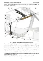
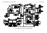
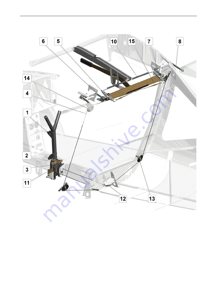
Fig. 7. Control system of flaperons (drooping ailerons)
The control force applied by the pilot to the control stick (1) is passed via the lever (2) to the
cables (4) by cable’s terminals (3). Then via the cables (4) the force is passed to the inner
right and left (5) bellcranks, via the inner pushrods (6) to the outer left and right (7)
bellcranks. Then the control force is passed from the outer bellcranks to the flaperons via
the outer pushrods (8). The inner bellcranks hinged on the flap extension mechanism beam
are connected to each other with the pushrod (10). The cables are routed using two pulleys
(12) on aft of the frame No.3 low in the middle, two pulleys (13) on aft of the frame No.3 low
on the sides, and two pulleys (14) on the frame No.3 up near the rear wing attachment
points.
The cable tension and flaperon position adjustment is achieved using the turnbuckles (15)
located near the inner rockers (5).
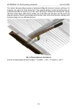
Deflection angles of the flaperons (as ailerons): up
– 15.5±1°, down – 11.1±1°.

