AEROMASTER Extra330L-50CC Instruction Manual Download Page 21

21

Lets go over the airframe and perform a pre-flight to make sure everything is in order.

This concludes your pre-flight checks.  After your maiden flight, repeat these steps to  perform a post flight to
ensure nothing has loosened. It s always a good habit  to use a checklist like this one to go   over your aircraft
prior to the first flight of the day.
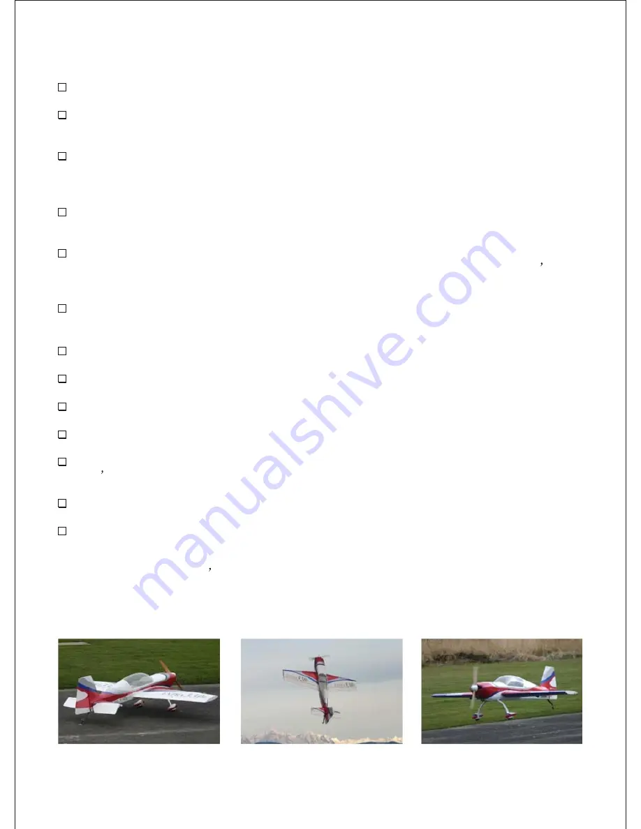
Flying!

Inspect the airframe for any visible damage and loose covering that may have occurred during assembly.

Inspect the main landing gear and tail wheel assembly.  Ensure all mounting hardware and collars are
fastened properly.

Inspect your motor installation and cowl to ensure all bolts are  tight and the muffler is firmly mounted in
place.  Check the motor and muffler for possible contact with the cowl.  Inspect ignition module and
spark plug wire for proper mounting.  Check propeller and spinner to ensure they are both secure.

Inspect the inside of the fuselage to ensure your  batteries, switches, regulators (if equipped), fuel tank
and lines are securely fastened.  Check nylon wing bolts to ensure they are in place and secured.

Inspect all control surfaces and control surface hardware.  Gently tug on each surface to make sure the
hinges are properly bonded.  Check the four 4/40 horizontal stabilizer fasteners and ensure they re in
place and secured.

Check all servos for mounting screws.  Check servo arm mounting screws and inspect that the 4/40 links
have been secured with lock nuts.

Fill fuel tank and inspect for any leaks.

Check your batteries in both your aircraft and radio to ensure  they are fully charged

Turn on radio to inspect all  controls for binding, proper direction and throw while on high rates.

Re-check CG.    It should be anywhere from 5 to 6 -1/2 inches depending on your flying style.

Secure aircraft using a buddy or hold down and start motor according to manufacturers guidelines.
Don t forget to lower your throttle prior to ignition.

Perform a proper range check with the motor running using your radio manufacturers instructions.

Make sure you go  back to low rates for your maiden takeoff and enjoy!

Summary of Contents for Extra330L-50CC

Page 1: ...n Extra300L fitted with a more powerful 330hp Lycoming AEIO 540 engine these aircraft have been nicknamed the Extra330L Our aircraft was designed with 1 420 sq inches of wing area while keep the total weight to a minimum Whether you want an aircraft precise enough to compete in IMAC or3d until yourairsick we believe our Extra fits the bill It s light weight gives you the stability in high alpha to...

Page 2: ...llation Chapter 7 Control Surface and Hardware Installation Chapter 8 Radio and Control Surface Setup Chapter 9 Final Inspection and Pre Flight Additional items needed to complete this aircraft which are not included An engine within the recommend range and propeller 6 channel computer radio and receiver recommended Batteries and switches with regulators if using Ion batteries Two aileron servos r...

Page 3: ...t and 1 left 2 Elevators 1 right and 1 left 1 Rudder 1 Fiberglass Cowl 1 Pair of fiberglass wheel pants 1 Composite landing gear 1 Pair of wheels 1 Tail wheel and tiller assembly 1 Carbon fiber wing tube 1 1 4 inch 1 1 Carbon fiber stabilizer tube 2 inch 2 Nylon wing retention bolts 1 Carbon fiber pushrod 8 Metal pushrod ends 1 aluminum control horn set 1 20oz fuel tank 6 4 40 ball links 1 Set of ...

Page 4: ...to ensure task completion 1 Go over you model as necessary with a covering iron to insure all joints seams and corners are sealed properly figure 1 2 Use your iron to ensure the areas where cutouts are needed for your hardware are located and sealed down such as servos tubes and control horn mounting locations figure 2 Next we ll need to cut out the covering at the locations for hardware and final...

Page 5: ... can damage the composite landing gear and cause it to fail Only tighten enough to lock the axle firmly in place and not rotate Loc tite is not recommended here as it will damage the nylon bushing figure 6 2 Slide one wheel collar or a 8mm piece of fuel tubing to the inside of each axle This acts as a spacer preventing the wheels from moving side to side and making contact against the inside of th...

Page 6: ...e while keeping the bottom of the wheel opening level with your work surface and mark your hole locations through the mounting holes in the landing gear Repeat this step for the other side figure 11 4 Drill the holes for the 4 40 bolts in the wheel pants at the locations you ve marked 5 Apply some white wood glue to the inner side of the four 4 40 blind nuts and install the blind nuts to the insid...

Page 7: ...etscrew of the wheel collars figure 18 8 Place a piece of low tack masking tape over the tail wheel bracket mounting block Mark the centerline over the tape on the tail wheel bracket mounting block figure 19 9 Place the tail wheel bracket on the mounting block ensuring the bracket holes line up with the centerline and mark the hole locations for the two large wood screws figure 20 10 Once your loc...

Page 8: ...2 x bolts withspring andflat washers 4 Not Provided 1 2 inch low tack masking tape Drilland smalldrill bitfor woodscrews Canopyglue iptional 1 Install the hatch on the fuselage using four 4 40 bolts with spring and flat washers provided figure28 2 Trial fit the canopy to the fuselage access hatch to determine screw locations 3 Mark evenly spaced locations for the screws using at least six per side...

Page 9: ...t fit and install the Canopy Hatch on the fuselage using the 3 four 4 40 x bolts with spring and flat washers provided If 4 satisfied remove and set aside hatch for cowling installation figure 33 1 7 For the cowling drill two holes in the bottom for the two 6 32 x 2 bolts from inside the cowling using the cowl ring holes as a guide figure 29 1 8 Install the comling using the four 6 32 x 2 bolts sp...

Page 10: ...tarted What you will need in thischapter Firewall and Fuse Triangle stock included with the kit Not Provided 30 to 45 minute epoxy An engine in the recommend size range 1 3 2 inch spinner Propeller A drill and drill bits Center punch A 12 square 1 2 inch tape for DA 50 template White wood glue such as Elmer for BME 50 With the engine is installed you will want approximately 6 13 16 inchesfrom the ...

Page 11: ...aper template to the size needed to tape it to the firewall using the pre marked thrust line and offset centerline as a guide figure 43 4b Using a center punch place it in each crosshair and mark each location Drill 1 out the four holes for 20 bolts figure 44 and 45 4 5 Temporarily mount the motor to the firewall figure 46 Trial fit the firewall to the motor box ensuring that the bottom of the fir...

Page 12: ... contact from the throttle choke to the servos 2 56 Ball links for 4 40 rod not included will prevent the aforementioned metal to metal contact and will bolt to nicely to your motors carburetor 10 Mount engine for cowl installation figures 49 or 50 Chapter6 Cowlinginstallation Place an to ensure task completion Always wear a mask and eye protection while cutting fiberglass Take your time while ins...

Page 13: ...t at least an extra 1 4 inch cut around any of the engine components that protrude Mark any additional areas that may require trimming figure 55 4 Remove the cowling and cut out the remaining areas to be trimmed If satisfied install the cowling propeller and spinner figure 56 and 57 Chapter 7 Control Surface and Hardware Installation Weare pleased to now providehigh quality aluminum control hornas...

Page 14: ...servo arms We used high quality aluminum 1 25 inch arms on the aileron servos 1 25 inch arms on elevator servos and one 3 inch arm for the rudder You can also install your 4 40 ball links and pushrod ends to the elevator and aileron servo arms prior to mounting the servo arms to the servo 1 Install 130oz or better servos for the elevators in the servo trays located in the rear of the fuselage Make...

Page 15: ...ring with the top of the surface flat on your work surface figure 65 and 66 3 7 For the rudder measure 1 from the 4 1 bottom and a inch back and mark the 4 location Measure half the width on the leading edge of the control surface just in front of the horn location and place it flat on your drilling surface Raise the trailing edge of the surface the same distance to achieve a vertical entry for yo...

Page 16: ...5 degrees for all others figure 76 13 Use some masking tape to hold the surfaces together and let cure for at least eight hours Repeat these steps until all of the surfaces are epoxied in place figure 77 14 Install the tiller springs you set aside in chapter 2 to the tiller horn and tiller Tip 4 Optional step After your epoxy has cured itwould be a good time to seal all of your hinge gaps prior to...

Page 17: ...ds needed to the proper length using a mask using care not to breath any of the CF dust Take masking tape and single wrap the area to be cut We recommend using a small hand saw while rotating the rod until it falls away cleanly ADremel tool or similar will work but it tends spread more dust figure 85 22 Remove the tape from the pushrods and test fit the rods and make sure your surfaces are still c...

Page 18: ...gain the choice is yours You can buy this inexpensive cable and crimps at most sporting goods stores or boating supply outlets 24 Install yourpull pullcable Ensurethedistanceof the cableisequalon bothsides Also the distancebetweenthe twohornsonthe ruddershouldbethe samedistanceasit is on theservoarm For example we useda3 incharm witheachcableplaced at1 5incheson each side Rotatethehornsin untilthe...

Page 19: ...would be a good time to apply the optional vinyl graphics included with the kit Make sure you apply the vinyl in a warm room and the surface area is clean where the graphics are to be applied 29 First remove the backing from the clear transfer tape and place it on a clean work surface tact side up Apply the vinyl graphic face down on the transfer tape Use a credit card or similar and press down on...

Page 20: ...ensure task completion What you will need in this chapter Completedairframe Radio Throw templatesor meter 1 Set your throws accordingly Double check to make sure nothing is binding to include the throttle and or choke servos and their linkages Also ensure all surfaces and controls are moving in the proper directions Chapter 10 Final Inspection and Pre Flight Welcome to the final chapter prior to y...

Page 21: ...tteries switches regulators if equipped fuel tank and lines are securely fastened Check nylon wing bolts to ensure they are in place and secured Inspect all control surfaces and control surface hardware Gently tug on each surface to make sure the hinges are properly bonded Check the four 4 40 horizontal stabilizer fasteners and ensure they re in place and secured Check all servos for mounting scre...

Page 22: ...will deliver the smooth performance the Extra is known for On high rates it delivers incredible 3d with a style and heart pumping excitement that only an Extra can deliver We like our CG setup around 5 1 2 to 6 inches for all around performance For contest flying such as IMAC 5 inches offers good precision and our airframe is a great choice We hope this aircraft provides you many years of enjoymen...

Reviews: