


MAINTENANCE MANUAL
IFR 4000
2-2-1
Page 6
Aug 1/04
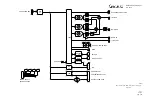
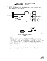
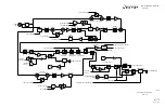
(3) Frequency
Counter
The Frequency counter measures the frequency of the detected 100 to 400 MHz RF
carrier and is a general purpose counter via the AUX Connector. The RF carrier is run
through a limiter and then a prescaler in the RF Assy. The pre-scaled output is run to
the Multi-Function PCB Assy. The frequency counter consists of a 24-bit duration
counter and a 32-bit frequency counter. The duration counter runs at 1 MHz and is
used to gate the measurement window for the frequency counter. The duration counter
requires two writes by the processor to program the duration counter. The lower
16-bits are located on data lines D31-D16 at address 40022000. The upper 8-bits are
located on data lines D23-D16 at address 40022002. The value written to the counter
is calculated as n-1, where n is the number of 1 MHz cycles in the duration. Zero (0)
is an invalid value and is not used. For a duration of 200 ms, the value 30D3Fh is
written to the 24-bit counter. D3Fh is written to the lower address and 3h is written to
the upper address. Bit D18 in the control register controls the operation of the
frequency counter. When Bit D18 is set to 1, the frequency counter is held in reset.
When Bit D18 is set low, the frequency counter runs continuously.
When a measurement has been completed and new data is available, the
FCTR_READY signal (Bit D21) in the status register is set high. Bit D21 remains high
until the data has been read. The data remains valid from when the signal goes high
until the end of the next gate time, at that point, the registers are updated with the
new data. This requires that the data be read prior to the next value getting written to
the holding registers.
The counter data is read at address locations 40022004 and 40022006h. The lower
16-bits are contained at address location 40022004h and the upper 16-bits are
contained in address location 40022006h. Since the frequency counter input signal is
used to terminate the gate window, a value of one (1) must be subtracted from the
value read.
At default, the frequency counter is set to count for a 200 ms window and the prescaler
is set to divide the incoming signal by 100. This setup limits the incoming signal from
the RF Assy to a maximum of 4 MHz.
(4) RF Control and Status
The RF control circuitry consists of status inputs, a serial bus control register, two
data registers, a start register and a latch pulse register. The four status inputs from
the RF are read in the FPGA status register. A state change in any one of the four
inputs (low to high or high to low) generates an interrupt. The RF serial bus control
register is used to select which device gets loaded, the bit ordering for the serial
transmission of data, positive or negative clocking of the data, 16 or 24-bit word length
and manual control for the M-Bus SCL and SDA lines. The start register causes the
serial data to begin transmitting.
Data Register #1 (address location 40023000h) contains the serial data for the 16-bit
word and also the lower 16 bits of the 24-bit word. Data Register #2 (address location
40023002h) contains the serial data of the upper byte of the 24-bit word. Data
Register #2 is located on data lines D23-D16. The two registers can be written in any
order. The start register (address locati on 40023006h) is used to initiate the serial
data output sequence. Data written to the start register is retransmitted.
Summary of Contents for IFR 4000
Page 1: ...NAV COMM Test Set Maintenance Manual 1002 5600 4P0 IFR 4000...
Page 3: ...MAINTENANCE MANUAL IFR 4000 FOR QUALIFIED SERVICE PERSONNEL ONLY...
Page 4: ...MAINTENANCE MANUAL IFR 4000 THIS PAGE INTENTIONALLY LEFT BLANK...
Page 6: ...MAINTENANCE MANUAL IFR 4000 THIS PAGE INTENTIONALLY LEFT BLANK...
Page 12: ...MAINTENANCE MANUAL IFR 4000 INTRODUCTION Page 2 Aug 1 04 THIS PAGE INTENTIONALLY LEFT BLANK...
Page 32: ...MAINTENANCE MANUAL IFR 4000 2 2 1 Page 14 Aug 1 04 THIS PAGE INTENTIONALLY LEFT BLANK...
Page 34: ...MAINTENANCE MANUAL IFR 4000 2 2 1 Page 16 Aug 1 04 THIS PAGE INTENTIONALLY LEFT BLANK...
Page 42: ...MAINTENANCE MANUAL IFR 4000 2 2 2 Page 8 Aug 1 04 THIS PAGE INTENTIONALLY LEFT BLANK...
Page 108: ...MAINTENANCE MANUAL IFR 4000 2 2 4 Page 2 Aug 1 04 THIS PAGE INTENTIONALLY LEFT BLANK...
Page 160: ...MAINTENANCE MANUAL IFR 4000 2 2 4 Page 54 Aug 1 04 THIS PAGE INTENTIONALLY LEFT BLANK...
Page 166: ...MAINTENANCE MANUAL IFR 4000 2 3 1 Page 6 Aug 1 04 STEP PROCEDURE 4 Remove the Fuse...
Page 186: ...MAINTENANCE MANUAL IFR 4000 APPENDIX B Page 2 Aug 1 04 THIS PAGE INTENTIONALLY LEFT BLANK...
Page 188: ...MAINTENANCE MANUAL IFR 4000 APPENDIX C Page 2 Aug 1 04 THIS PAGE INTENTIONALLY LEFT BLANK...
Page 200: ...MAINTENANCE MANUAL IFR 4000 APPENDIX D Page 12 Aug 1 04 THIS PAGE INTENTIONALLY LEFT BLANK...
Page 206: ...MAINTENANCE MANUAL IFR 4000 APPENDIX E Page 6 Aug 1 04 THIS PAGE INTENTIONALLY LEFT BLANK...