


MAINTENANCE MANUAL
IFR 4000
2-2-3
Page 63
Aug 1/04
(4) Modulation
PREREQUISITES:
Test Setup (para 2-2-3F(1)
Miscellaneous (para 2-2-3F(2)
RF Amplitude Levels (para 2-2-3F(3)
TEST EQUIPMENT:
Measuring Receiver w/ Sensor Head
Digital Multimeter (DMM)
STEP PROCEDURE
1. From the Calibration Screen, press the MOD CALS Soft Key to enter the
MODULATION CAL Screen.
VOR
2. Press the VOR Soft Key to display the VOR CAL Sequence Screen.
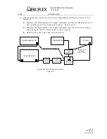
3. Connect Measuring Receiver Sensor Head to the ANT Connector.
4. Select AM on the Measuring Receiver as necessary. (For AM measurements,
use the Peak
±
/2 detector, and the 3 kHz Low-Pass Filter. Use no High Pass
filtering.)
5. Follow the on-screen prompts and recall stored calibration levels on the
Measuring Receiver as needed. For the VOR CAL Sequence, the AM modulation
setting error must be <0.5% and the amplitude setting error must be <0.1 dB.
6. Reference the following:
z
Step 1 of VOR CAL Sequence
Select 3 kHz Low-Pass Filter on the Measuring Receiver.
z
Step 2 of VOR CAL Sequence
Select 15 kHz Low-Pass Filter on the Measuring Receiver.
z
Step 3 of VOR CAL Sequence
Select 3 kHz Low-Pass Filter on the Measuring Receiver.
7. When the VOR CAL Sequence is complete, press the SAVE & RETURN Soft Key
to return to the MODULATION Cal Screen.
MAIN LOC
8. Press the MAIN LOC Soft Key to display the MAIN PATH LOC Sequence Screen.
9. Connect Digital Multimeter to the AUX I/O Connector. Set DMM to read AC
Volts.
10. Follow the on-screen prompts.
11. When the MAIN PATH LOC Sequence is complete, press the SAVE & RETURN
Soft Key to return to the MODULATION Cal Screen.
MAIN G/S
12. Press the MAIN G/S Soft Key to display the MAIN PATH G/S Sequence Screen.
13. Connect Measuring Receiver Sensor Head to the ANT Connector.
14. Set Measuring Receiver input frequency to 332.000 MHz. (For AM
measurements, use the 3 kHz Low-Pass Filter. Use no High Pass filtering.)
15. Follow the on-screen prompts.
Summary of Contents for IFR 4000
Page 1: ...NAV COMM Test Set Maintenance Manual 1002 5600 4P0 IFR 4000...
Page 3: ...MAINTENANCE MANUAL IFR 4000 FOR QUALIFIED SERVICE PERSONNEL ONLY...
Page 4: ...MAINTENANCE MANUAL IFR 4000 THIS PAGE INTENTIONALLY LEFT BLANK...
Page 6: ...MAINTENANCE MANUAL IFR 4000 THIS PAGE INTENTIONALLY LEFT BLANK...
Page 12: ...MAINTENANCE MANUAL IFR 4000 INTRODUCTION Page 2 Aug 1 04 THIS PAGE INTENTIONALLY LEFT BLANK...
Page 32: ...MAINTENANCE MANUAL IFR 4000 2 2 1 Page 14 Aug 1 04 THIS PAGE INTENTIONALLY LEFT BLANK...
Page 34: ...MAINTENANCE MANUAL IFR 4000 2 2 1 Page 16 Aug 1 04 THIS PAGE INTENTIONALLY LEFT BLANK...
Page 42: ...MAINTENANCE MANUAL IFR 4000 2 2 2 Page 8 Aug 1 04 THIS PAGE INTENTIONALLY LEFT BLANK...
Page 108: ...MAINTENANCE MANUAL IFR 4000 2 2 4 Page 2 Aug 1 04 THIS PAGE INTENTIONALLY LEFT BLANK...
Page 160: ...MAINTENANCE MANUAL IFR 4000 2 2 4 Page 54 Aug 1 04 THIS PAGE INTENTIONALLY LEFT BLANK...
Page 166: ...MAINTENANCE MANUAL IFR 4000 2 3 1 Page 6 Aug 1 04 STEP PROCEDURE 4 Remove the Fuse...
Page 186: ...MAINTENANCE MANUAL IFR 4000 APPENDIX B Page 2 Aug 1 04 THIS PAGE INTENTIONALLY LEFT BLANK...
Page 188: ...MAINTENANCE MANUAL IFR 4000 APPENDIX C Page 2 Aug 1 04 THIS PAGE INTENTIONALLY LEFT BLANK...
Page 200: ...MAINTENANCE MANUAL IFR 4000 APPENDIX D Page 12 Aug 1 04 THIS PAGE INTENTIONALLY LEFT BLANK...
Page 206: ...MAINTENANCE MANUAL IFR 4000 APPENDIX E Page 6 Aug 1 04 THIS PAGE INTENTIONALLY LEFT BLANK...